EasyManua.ls Logo

Mitsubishi Electric MSC-GA25VB-E1 User Manual

Mitsubishi Electric MSC-GA25VB-E1
24 pages
To Next Page IconTo Next Page
Page #1 background imageLoading...
Page #1 background image
SERVICE MANUAL
CONTENTS
1. TECHNICAL CHANGES ····································3
2. PART NAMES AND FUNCTIONS······················3
3. SPECIFICATION·················································5
4. NOISE CRITERIA CURVES·······························6
5. OUTLINES AND DIMENSIONS ·························7
6. WIRING DIAGRAM ············································8
7. REFRIGERANT SYSTEM DIAGRAM················8
8. SERVICE FUNCTIONS ······································9
9. TROUBLESHOOTING······································11
10. DISASSEMBLY INSTRUCTIONS·····················18
11. PARTS LIST······················································20
12. OPTIONAL PARTS···········································22
Wireless type
Models
MSC-GA20VB -
(WH)
MSC-GA25VB -
(WH)
MSC-GA35VB -
(WH)
E1
E1
E1
MSC-GA20VB -
MSC-GA25VB -
MSC-GA35VB -
E1
E1
E1
No. OB385
SPLIT-TYPE, AIR CONDITIONERS
SPLIT-TYPE, HEAT PUMP AIR CONDITIONERS
Indication of model name
NOTE:
•This manual describes technical data of indoor units.
•As for outdoor units MU-GA20/GA25/GA35VB - , refer to the service manual OB386.
•As for outdoor units MUH-GA20/GA25/GA35VB - , refer to the service manual OB387.
•As for outdoor units MUX-2A28/2A59/3A60/3A63/2A70/4A73VB - , refer to the service manual
OB384.
•As for outdoor units MXZ-A14/A18/A26/A32WV - , refer to the service manual OB319 REVISED
EDITION-A.
E1
E1
E1
E1
OB385-1.qxp 05.1.25 18:50 Page 1
Question and Answer IconNeed help?

Do you have a question about the Mitsubishi Electric MSC-GA25VB-E1 and is the answer not in the manual?

Mitsubishi Electric MSC-GA25VB-E1 Specifications

General IconGeneral
BrandMitsubishi Electric
ModelMSC-GA25VB-E1
CategoryAir Conditioner
LanguageEnglish

Summary

1 TECHNICAL CHANGES

MSC-A07YV-E1 MSC-GA20VB-E1

Details technical changes specific to the MSC-GA20VB model.

MSC-A09YV-E1 MSC-GA25VB-E1

Details technical changes specific to the MSC-GA25VB model.

MSC-A12YV-E1 MSC-GA35VB-E1

Details technical changes specific to the MSC-GA35VB model.

2 PART NAMES AND FUNCTIONS

INDOOR UNIT

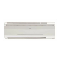
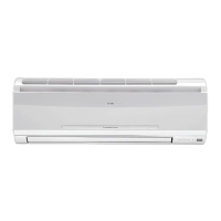
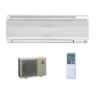
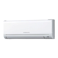
Identifies and illustrates various parts of the indoor unit for reference.

ACCESSORIES

<Indoor unit>

Lists all included accessories for the indoor unit.

REMOTE CONTROLLER

Remote Controller Operation

Explains the operation and features of the remote controller.

3 SPECIFICATION

4 NOISE CRITERIA CURVES

5 OUTLINES AND DIMENSIONS

6 WIRING DIAGRAM

MODELS WIRING DIAGRAM

Provides electrical wiring schematics for the indoor unit models.

7 REFRIGERANT SYSTEM DIAGRAM

INDOOR UNIT

Illustrates the refrigerant circuit and flow for the indoor unit.

8 SERVICE FUNCTIONS

8-1 TIMER SHORT MODE

Explains how to shorten timer settings for service purposes.

8-2 P.C. BOARD MODIFICATION FOR INDIVIDUAL OPERATION

Details P.C. board modifications for individual remote operation of multiple units.

8-3 REMOTE CONTROLLER (How to set the type)

Guide on setting the remote controller type for correct operation.

8-4 MU & MUX TYPE / MUH & MXZ TYPE SWITCH OVER AND AUTO RESTART FUNCTION

How to release "AUTO RESTART FUNCTION"

Instructions on how to disable the auto restart feature.

9 TROUBLESHOOTING

9-1 Cautions on Troubleshooting

Essential safety and preparatory steps before troubleshooting.

3 Troubleshooting procedure

Outlines the general steps for diagnosing unit problems.

4 How to replace batteries

Instructions for replacing batteries in the remote controller.

NOTE2: INFORMATION FOR MULTI SYSTEM AIR CONDITIONER

Specific information and indicators for multi-system AC units.

9-2 Instruction of troubleshooting

9-3 Troubleshooting check table

9-4 Trouble criterion of main parts

9-5 Troubleshooting flow

Check of remote controller and receiver P.C. board

Steps to diagnose issues with the remote control system.

Check of indoor electronic control P.C. board

Procedures for visually inspecting and testing the indoor control board.

When OPERATION INDICATOR lamp flashes 0.5-second intervals or 1-time.

How to check mis-wiring and serial signal error

Guide to check for wiring errors and serial signal communication issues.

9-6 Test point diagram and voltage

10 DISASSEMBLY INSTRUCTIONS

Terminal with locking mechanism Detaching points

General procedures for detaching terminals with locking mechanisms.

1 Removing the front panel

Step-by-step guide for safely removing the front panel.

2 Removing the electronic control P.C. board and the power monitor, receiver P.C. board

Instructions for removing the control and power monitor boards.

3 Removing the electrical box

4 Removing the nozzle assembly and the vane motor

Guide for removing the nozzle assembly and vane motor.

5 Removing the indoor fan motor and the line flow fan

Procedure for removing the indoor fan motor and line flow fan.

11 PARTS LIST

11-1 INDOOR UNIT STRUCTURAL PARTS

Lists the main structural components of the indoor unit.

11-2 ACCESSORY AND REMOTE CONTROLLER

Lists parts for accessories and the remote controller.

11-3 INDOOR UNIT ELECTRICAL PARTS AND FUNCTIONAL PARTS

11-4 INDOOR UNIT HEAT EXCHANGER

Lists components related to the indoor unit's heat exchanger.

12 OPTIONAL PARTS

AIR CLEANING FILTER

Information on the optional air cleaning filter, its benefits, and usage.

Related product manuals