EasyManua.ls Logo

Mitsubishi Electric MSH-07NV User Manual

Mitsubishi Electric MSH-07NV
80 pages
To Next Page IconTo Next Page
Page #1 background imageLoading...
Page #1 background image
SERVICE MANUAL
SPLIT-TYPE,HEAT PUMP AIR CONDITIONERS
CONTENTS
1. TECHNICAL CHANGES ····································2
2. PART NAMES AND FUNCTIONS······················3
3. SPECIFICATION·················································6
4. OUTLINES AND DIMENSIONS ······················ 11
5. WIRING DIAGRAM ··········································15
6. REFRIGERANT SYSTEM DIAGRAM··············24
7. PERFORMANCE CURVES······························29
8. MICROPROCESSOR CONTROL ····················33
9. SERVICE FUNCTIONS ····································44
10. TROUBLESHOOTING······································47
11. DISASSEMBLY INSTRUCTIONS·····················60
12. PARTS LIST······················································70
13. OPTIONAL PARTS ····································BACK
Wireless type
Models
MSH-07NV -
(
WH
)
· MUH-07NV -
MSH-09NV -
(
WH
)
· MUH-09NV -
MSH-12NV -
(
WH
)
· MUH-12NV -
MSH-18NV -
(
WH
)
· MUH-18NV -
MSH-24NV -
(
WH
)
· MUH-24NV -
MSH-07NV -
(
WH
)
· MUH-07NV -
MSH-09NV -
(
WH
)
· MUH-09NV -
MSH-12NV -
(
WH
)
· MUH-12NV -
MSH-18NV -
(
WH
)
· MUH-18NV -
MSH-24NV -
(
WH
)
· MUH-24NV -
MSH-18NV -
(
WH
)
· MUH-18NV -
E3E3
E2E2
E2E2
E2E2
E2E2
E2E2
E1E1
E1E1
E1E1
E1E1
E1E1
No. OB207
MSH-18NV -
MSH-18NV -
MSH-18NV -
E3
E2
E1
This Servise Manual OB207 deals with MSH-07/09/12/18/24NV-E1,
MUH-07/09/12/18/24NV-E1, MSH-18NV-E2, and MUH-18NV-E2 in
OB176 REVISED EDITION-A issued in July in1997.
Therefore, please refer to OB207, not to OB176 REVISED
EDITION-A, for the above models.
Refer to the Service Manual OB185 when MSH-07/09/12NV- , MSH-07/09/12/18NV- , and MSH-18NV-
are connected with MXZ-32NV- as multi system units.
E1
E3E2E1
OB207t-1qxp 25/9/97 8:51 PM Page 1
Question and Answer IconNeed help?

Do you have a question about the Mitsubishi Electric MSH-07NV and is the answer not in the manual?

Mitsubishi Electric MSH-07NV Specifications

General IconGeneral
BrandMitsubishi Electric
ModelMSH-07NV
CategoryAir Conditioner
LanguageEnglish

Summary

1 TECHNICAL CHANGES

2 PART NAMES AND FUNCTIONS

Indoor Unit Part Identification

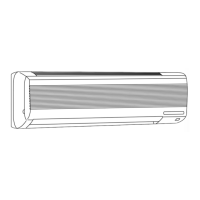
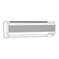
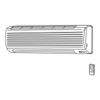
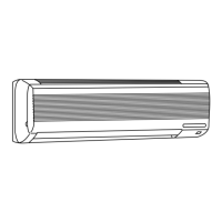
Identifies and labels the various parts of the indoor unit.

Outdoor Unit Part Identification

Identifies and labels the various parts of the outdoor unit.

REMOTE CONTROLLER OVERVIEW

3 SPECIFICATION

4 OUTLINES AND DIMENSIONS

Indoor Unit Dimensions

Provides diagrams and dimensions for the indoor unit.

Outdoor Unit Dimensions

Provides diagrams and dimensions for the outdoor unit.

5 WIRING DIAGRAM

Indoor Unit Wiring Diagram

Details the wiring connections for the indoor unit.

Outdoor Unit Wiring Diagram

Details the wiring connections for the outdoor unit.

6 REFRIGERANT SYSTEM DIAGRAM

MSH/MUH-07/09NV Refrigerant System Diagrams

Illustrates refrigerant circuits for MSH/MUH-07/09NV models.

MSH/MUH-12NV & MSH/MUH-18NV Refrigerant System Diagrams

Illustrates refrigerant circuits for MSH/MUH-12NV and 18NV models.

MSH/MUH-24NV Refrigerant System Diagrams

Illustrates refrigerant circuits for MSH/MUH-24NV models.

7 PERFORMANCE CURVES

Guaranteed Voltage and Air Flow

Specifies voltage range and recommended air flow settings.

Main Performance Readings

Lists key readings for performance curve analysis.

OUTDOOR UNIT PERFORMANCE DATA

8 MICROPROCESSOR CONTROL FEATURES

Remote Controller and Basic Operations

Details remote controller functions and basic operations.

Operation Modes (COOL, DRY, HEAT)

Explains the COOL, DRY, and HEAT operation modes.

Timer and Emergency Operations

Covers timer settings and emergency test operation procedures.

9 SERVICE FUNCTIONS

Service Modes and Procedures

Explains service modes like compulsory defrost and timer short mode.

AUTO RESTART FUNCTION

10 TROUBLESHOOTING GUIDE

Troubleshooting Cautions and Procedure

Provides troubleshooting cautions, checks, and general procedure.

Remote Controller Battery Replacement

Instructions on how to replace batteries in the remote controller.

DIAGNOSTIC FLOWCHARTS AND TABLES

Troubleshooting Flowcharts and Tables

Contains flowcharts, check tables, and trouble criteria for diagnosis.

COMPONENT CHECKS AND TEST POINTS

Component Checks

Guides for checking specific unit components like fan motor and boards.

Test Point Diagrams and Voltages

Provides diagrams for test points and voltage measurements.

11 DISASSEMBLY INSTRUCTIONS

Indoor Unit Disassembly Procedures

Detailed steps for disassembling the indoor unit components.

Outdoor Unit Disassembly Procedures

Detailed steps for disassembling the outdoor unit components.

12 PARTS LIST

Indoor Unit Parts List

Comprehensive list of parts for the indoor unit.

Outdoor Unit Parts List

Comprehensive list of parts for the outdoor unit.

Accessory and Remote Controller Parts List

Lists available accessories and remote controller parts.

13 OPTIONAL PARTS

Optional Refrigerant Pipes

Details optional refrigerant pipes with specifications and part numbers.

Optional Filters

Information on optional air cleaning and deodorizing filters.

Related product manuals