EasyManua.ls Logo

Mitsubishi Electric MSH09TW User Manual

Mitsubishi Electric MSH09TW
129 pages
To Next Page IconTo Next Page
Page #1 background imageLoading...
Page #1 background image
SERVICE MANUAL
SPLIT-TYPE, HEAT PUMP AIR CONDITIONERS
CONTENTS
1. FEATURES·························································2
2. TECHNICAL CHANGES ····································5
3. PART NAMES AND FUNCTIONS······················7
4. INDOOR UNIT COMBINATION························10
5. SPECIFICATION···············································11
6. DATA·································································17
7. OUTLINES AND DIMENSIONS ·······················39
8. WIRING DIAGRAM ··········································43
9. REFRIGERANT SYSTEM DIAGRAM··············51
10. MICROPROCESSOR CONTROL ····················54
11. SERVICE FUNCTIONS·····································72
12. TROUBLESHOOTING······································75
13. DISASSEMBLY INSTRUCTIONS···················101
14. PARTS LIST····················································114
15. OPTIONAL PARTS·········································126
Wireless type
Models
MSH09TW · MUH09TW
MSH12TN · MUH12TN
MSH15TN · MUH15TN
MSH17TN · MUH17TN
MSH09TW
-
· MUH09TW
-
MSH12TN
-
· MUH12TN
-
· MUH12TN
-
MSH15TN
-
· MUH15TN
-
· MUH15TN
-
MSH17TN
-
· MUH17TN
-
U1U1
U2
U1U1
U2
U1U1
U1U1
No. OB275
REVISED EDITION-D
The Slim Line.
From Mitsubishi Electric.
L
I
S
T
E
D
CUS
MSH12TN
MSH15TN
MSH17TN
INDOOR UNIT
MUH15TN
OUTDOOR UNIT
Remote
controller
MSH12TN -
MSH15TN -
MSH17TN -
U1
U1
U1
MUH15TN - MUH15TN -
U2U1
TM
Inverter-controlled multi system Model
· MXZ30TN
· MXZ30TN2
Revision:
MUH12TN- has been added.
MUH15TN- has been added.
REFRIGERANT SYSTEM DIAGRAM of
MXZ30TN and MXZ30TN2 has partly been
changed.
PARTS LIST of MXZ30TN and MXZ30TN2
has partly been changed
Please void OB275 Revised edition-C.
U2
U2
Indication of
model name
Indication of
model name
OB275--1.qxp 03.12.2 16:49 Page 1

Table of Contents

Question and Answer IconNeed help?

Do you have a question about the Mitsubishi Electric MSH09TW and is the answer not in the manual?

Mitsubishi Electric MSH09TW Specifications

General IconGeneral
BrandMitsubishi Electric
ModelMSH09TW
CategoryAir Conditioner
LanguageEnglish

Summary

FEATURES

DIFFERENT POINTS between models for USA and CANADA

Compares model differences for USA and Canada.

TECHNICAL CHANGES

PART NAMES AND FUNCTIONS

INDOOR UNIT

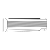
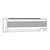
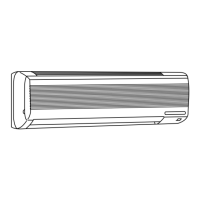
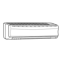
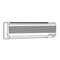
Details components of the indoor unit.

OUTDOOR UNIT

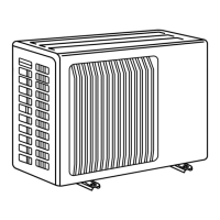
Details components of the outdoor unit.

REMOTE CONTROLLER

Explains the remote controller and its buttons.

INDOOR UNITS COMBINATION

SPECIFICATIONS

DATA

6-1. PERFORMANCE DATA

Presents cooling capacity performance data under various conditions.

6-2. COOLING CAPACITY CORRECTIONS

Details corrections for cooling capacity based on piping length.

3) HEATING CAPACITY

Provides heating capacity data for different voltage and temperature conditions.

6-2. PERFORMANCE CURVE

Shows performance graphs for cooling and heating.

6-3. Condensing pressure

Shows condensing pressure data for various models.

6-4. STANDARD OPERATION DATA

Provides standard operating parameters for various models.

6-5. OPERATING RANGE

Defines operational limits for power supply and operation.

(1) POWER SUPPLY

Specifies power supply ratings and guaranteed voltage.

(2) OPERATION

Details operating conditions and temperature ranges.

6-6. OUTLET AIR SPEED AND COVERAGE RANGE

Provides data on air outlet speed and coverage.

6-7. ADDITIONAL REFRIGERANT CHARGE (R22(oz.))

Details additional refrigerant charge based on pipe length.

6-8. CAPACITY AND THE INPUT CURVES

Shows capacity and input curves for different indoor unit classes.

6-9. Capacity and input correction by means of inverter output frequency

Illustrates capacity and input correction based on inverter frequency.

6-10. Outdoor low pressure and outdoor unit current

Shows graphs for outdoor low pressure and unit current.

(1) COOL operation

Details low pressure and current for cooling operation.

(2) HEAT operation

Details low pressure and current for heating operation.

OUTLINES AND DIMENSIONS

WIRING DIAGRAM

REFRIGERANT SYSTEM DIAGRAM

MICROPROCESSOR CONTROL

INDOOR UNIT DISPLAY SECTION

Explains the operation indicator lamp and its indications.

WIRELESS REMOTE CONTROLLER

Details the wireless remote controller and its buttons.

10-1. “I FEEL CONTROL” OPERATION

Explains the "I FEEL CONTROL" operation mode.

10-2. COOL OPERATION

Explains how to operate in COOL mode.

10-3. DRY OPERATION

Explains how to operate in DRY mode.

10-4. HEAT OPERATION

Explains how to operate in HEAT mode.

10-5. FAN MOTOR CONTROL<MSH09>

Details fan motor control for MSH09 models.

10-6. AUTO VANE OPERATION

Explains automatic vane operation and positioning.

10-7. TIMER OPERATION

Explains how to set and cancel timers.

10-8. EMERGENCY-TEST OPERATION

Explains emergency and test run operations.

10-9. INVERTER MULTI SYSTEM CONTROL

Describes the inverter multi-system control.

10-10. INVERTER MAIN POWER SUPPLY CIRCUIT

Details the inverter main power supply circuit.

10-10-1. Outline drawing of main power supply circuit

Shows the schematic of the main power supply circuit.

10-10-2. Outline of main power supply circuit

Explains the operation of the main power supply circuit.

10-10-3. Function of main parts

Lists and describes the functions of main parts in the power supply circuit.

10-11. Optimal voltage control

Explains optimal voltage control for compressor efficiency.

1. Optimal

Describes how compressor efficiency relates to optimal voltage.

2. How to determine the optimal voltage

Details the method for determining optimal voltage.

10-12. LEV control

Explains linear expansion valve control.

Determination of LEV standard opening in each indoor unit

Shows standard LEV opening based on conditions.

10-13. Operational frequency range

Defines operational frequency ranges for different modes and units.

10-14. Heat defrosting control

Explains conditions and procedures for heat defrosting.

10-15. High pressure protection

Details high pressure protection mechanisms.

10-16. Discharge temperature protection control

Explains protection based on discharge temperature.

10-17. Refrigerant recovery control on heating

Describes refrigerant recovery control during heating.

10-18. Outdoor fan control

Explains how outdoor fan speed is controlled.

SERVICE FUNCTIONS

11-1. COMPULSORY DEFROSTING MODE FOR SERVICE

Explains how to manually activate defrosting for servicing.

11-2. CHANGE IN DEFROST SETTING

Details how to change defrost settings.

11-3. TIMER SHORT MODE

Explains shortening timer operation time for service.

11-4. P.C. BOARD MODIFICATION FOR INDIVIDUAL OPERATION

Describes modifications for individual remote operation.

11-5. AUTO RESTART FUNCTION

Explains the auto restart function and its settings.

TROUBLESHOOTING

12-1. Cautions on troubleshooting

Provides important precautions before starting troubleshooting.

4. How to replace batteries

Details the procedure for replacing remote controller batteries.

12-2. Instruction of troubleshooting

Provides a general troubleshooting flow chart.

Check the outdoor unit LED indicator

Guide to checking the outdoor unit LED indicator for status.

1. Troubleshooting check table

Lists symptoms and corresponding troubleshooting steps.

Self check table

Provides a table for self-checking common issues indicated by the operation lamp.

2. Trouble criterion of main parts

Lists main parts and their resistance/voltage criteria for checking.

DISASSEMBLY INSTRUCTIONS

Indoor Unit Disassembly

Covers disassembly of indoor unit components like front panel, PCB, etc.

Removing the front panel

Details steps to remove the front panel.

Removing the electronic control P.C. board

Details steps to remove the electronic control P.C. board.

Removing the electrical box

Details steps to remove the electrical box.

Removing the vane motor

Details steps to remove the vane motor.

Removing the line flow fan and indoor fan motor

Details steps to remove the fan and motor.

Outdoor Unit Disassembly

Covers disassembly of outdoor unit components like cabinet, PCB, fan, compressor.

Removing the cabinet

Details steps to remove the outdoor unit cabinet.

Removing the deicer P.C. board

Details steps to remove the deicer P.C. board.

Removing the propeller fan and outdoor fan motor

Details steps to remove the propeller fan and motor.

Removing the compressor

Details steps to remove the compressor.

Removing the heat exchanger

Details steps to remove the heat exchanger.

Removing the 4-way valve

Details steps to remove the 4-way valve.

Removing the linear expansion valve

Details steps to remove the linear expansion valve.

Removing the reactor

Details steps to remove the reactor.

MXZ30TN/MXZ30TN2 Outdoor Unit Disassembly

Covers disassembly of MXZ30TN/MXZ30TN2 outdoor units.

Removing the compressor

Details steps to remove the compressor from MXZ units.

Removing the fan motor

Details steps to remove the fan motor from MXZ units.

Removing the 4-way valve

Details steps to remove the 4-way valve from MXZ units.

Removing the linear expansion valve

Details steps to remove the LEV from MXZ units.

Removing the reactor

Details steps to remove the reactor from MXZ units.

PARTS LIST

Indoor Unit Parts

Lists structural, electrical, and functional parts for indoor units.

Outdoor Unit Parts

Lists structural, electrical, and functional parts for outdoor units.

MXZ30TN/MXZ30TN2 Outdoor Unit Parts

Lists structural and functional parts for MXZ30TN/MXZ30TN2 outdoor units.

Accessories and Remote Controller

Lists accessories and remote controller parts.

OPTIONAL PARTS

15-1. REFRIGERANT PIPES

Details optional refrigerant pipes and their specifications.

15-2. AIR CLEANING FILTER

Describes the air cleaning filter and its maintenance.

15-3. DEODORIZING FILTER

Describes the deodorizing filter and its maintenance.

15-4. Different-diameter pipe

Lists different diameter pipes and their specifications.

Related product manuals