Do you have a question about the Mitsubishi Electric MSZ-AY25VGKP-E6 and is the answer not in the manual?
Lists included items and optional parts for the unit.
Allows reducing timer set times for service purposes.
Guides on assigning remote controllers to specific indoor units.
Describes the unit's ability to resume operation after power interruption.
Details the process for connecting the Wi-Fi interface to a network.
Explains how to adjust the room temperature sensor calibration.
Explains the features and layout of the wireless remote control.
Describes the indicators and status lights on the indoor unit.
Explains the cooling mode operation, including frost prevention.
Details the dehumidification mode and its specific operations.
Outlines the operation of the fan-only mode without cooling or heating.
Describes the heating mode, including cold air prevention and defrosting.
Explains how the unit automatically switches between COOL and HEAT modes.
Covers the control of horizontal and vertical vanes for airflow direction.
Details how to set and use the ON/OFF timers for unit operation.
Explains the programming of daily and weekly operating schedules.
Describes the function to reduce noise and dim indicators for quiet operation.
Explains the mode for saving and recalling preferred settings.
Describes how to lock operation settings to prevent accidental changes.
Details the air purification function and its operation.
Explains the self-cleaning cycle performed after cooling or dry operation.
Covers the procedure for manual operation and testing.
Explains the compressor protection mechanism against frequent restarts.
Lists important safety precautions and checks before starting troubleshooting.
Explains how to retrieve and interpret error codes stored by the unit.
Provides detailed diagnostic steps for specific operational problems.
Initial checks for unit operation, power, and remote signal reception.
Steps to diagnose and resolve issues with the Wi-Fi connectivity.
A table correlating indicator patterns with specific failure modes and remedies.
Provides resistance values and checks for key internal components.
Flowcharts to guide troubleshooting for specific component failures.
Diagnosing issues related to the indoor fan motor's operation.
Troubleshooting steps for the remote control and main control board.
Specific checks for the indoor control board and fan motor connections.
Procedures for verifying wiring integrity and communication signals.
Steps to troubleshoot the air purification function and its components.
Provides detailed schematics and voltage measurement points for diagnostics.
Instructions on how to disconnect electrical terminals with locking features.
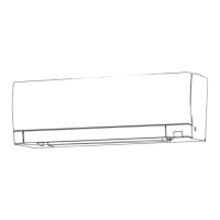
Detailed steps for removing various panels and internal components.
Instructions for removing the main external panels of the indoor unit.
Specific steps for detaching the right-side panel.
Specific steps for detaching the left-side panel.
Specific steps for detaching the front panel.
Specific steps for detaching the upper panel.
Procedure for safely removing the Wi-Fi interface module.
Instructions for correctly installing the Wi-Fi interface.
Steps to remove the electrical box and air purifying components.
Detailed steps for removing various circuit boards.
Procedure for removing the air outlet nozzle assembly.
Instructions for removing the motors controlling the vanes.
Steps to remove the fan, motor, and thermistor components.
Guidance on correctly installing the indoor coil thermistor.
| Cooling Capacity | 2.5 kW |
|---|---|
| Heating Capacity | 3.2 kW |
| Refrigerant | R32 |
| Energy Efficiency Class (Cooling) | A+++ |
| Energy Efficiency Class (Heating) | A++ |
| Weight (Outdoor Unit) | 28 kg |
| Power Supply | 220-240 V, 50 Hz |
| Outdoor Unit Weight | 28 kg |
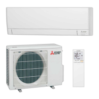
| Type | Air Conditioner |
| Indoor Unit Noise Level | 19 dB(A) |
| Noise Level (Outdoor Unit) | 46 dB |