Do you have a question about the Mitsubishi Electric MSZ-FH25VE - E1 and is the answer not in the manual?
| Cooling Capacity | 2.5 kW |
|---|---|
| Heating Capacity | 3.2 kW |
| Energy Efficiency Rating (Cooling) | A+++ |
| Energy Efficiency Rating (Heating) | A+++ |
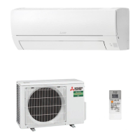
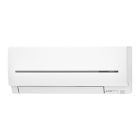
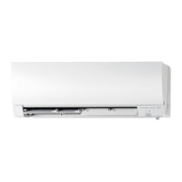
| Indoor Unit Dimensions (HxWxD) | 305 x 925 x 234 mm |
| Outdoor Unit Dimensions (HxWxD) | 550 x 800 x 285 mm |
| Refrigerant | R32 |
| Power Supply | 220-240 V, 50 Hz |
| Energy Efficiency Ratio (Cooling) | 5.15 |
| Sound Level (Indoor) | 19 dB |
| Energy Efficiency Ratio (Heating) | 5.1 |
| Noise Level (Indoor Unit) | 19 dB |
Shortens set time for compressor start, useful for service.
Assigns remote controllers to specific indoor units for multi-unit systems.
Configures the remote controller based on the indoor unit's installation location.
Details the operation, features, and protection modes for COOL mode.
Explains the DRY operation mode, including frost prevention and fan control.
Describes the FAN mode, where only the indoor fan operates.
Covers HEAT mode operation, including cold air prevention and high pressure protection.
Explains the automatic switching between COOL and HEAT modes based on temperature.
Details horizontal and vertical vane control for optimal airflow distribution.
Instructions for setting current time, ON/OFF timers, and program timers.
Guide for setting daily and weekly timer schedules for custom operation.
Describes the i-see sensor mode for temperature control and absence detection.
Fine-tuned airflow direction based on occupant location within i-see control.
Simulates natural wind airflow for enhanced comfort and exposure.
Explains the function of the built-in air purifying device.
Allows saving and recalling custom operation settings for convenience.
Details how to use the emergency operation switch for testing or emergencies.
Protects the compressor by delaying restart for 3 minutes after power interruption.
Important safety precautions and checks before performing troubleshooting.
Procedure to recall and check stored error codes for diagnosis.
General flowchart and guidance for diagnosing unit malfunctions.
Table correlating indicator lamp patterns with specific faults and remedies.
Specifies resistance values and checks for key internal components.
Detailed step-by-step flowcharts for diagnosing specific issues like fan motor errors.
Instructions for removing the front and side panels of the indoor unit.
Procedure to remove the electrical box containing P.C. boards and wiring.
Detailed steps for removing various electronic boards and assemblies.
Steps to remove the nozzle assembly containing vane motors.
Instructions for removing the vertical vane motor unit.
Steps for removing the horizontal vane motor unit.
Procedure for removing the air purifying device and its support.
Steps to remove the indoor fan motor, coil thermistor, and line flow fan.