Do you have a question about the Mitsubishi Electric MSZ-FH25VE2-E1 and is the answer not in the manual?
| Type | Split System |
|---|---|
| Cooling Capacity | 2.5 kW |
| Heating Capacity | 3.2 kW |
| Energy Efficiency Class (Cooling) | A+++ |
| Energy Efficiency Class (Heating) | A+++ |
| Indoor Unit Dimensions (H x W x D) | 305 x 925 x 234 mm |
| Outdoor Unit Dimensions (H x W x D) | 550 x 800 x 285 mm |
| Weight (Indoor Unit) | 13.5 kg |
| Refrigerant | R32 |
| Power Supply | 220-240 V, 50 Hz |
| Energy Efficiency Ratio (Cooling) | 5.15 |
| Noise Level (Outdoor Unit) | 46 dB(A) |
| Indoor Unit Weight | 13.5 kg |
| Indoor Unit Dimensions (WxHxD) | 925 x 305 x 234 mm |
| Outdoor Unit Dimensions (WxHxD) | 800 x 550 x 285 mm |
| Noise Level (Indoor Unit) | 19 dB(A) |
| Energy Efficiency Ratio (Heating) | 5.1 |
Details modifications and additions to the models covered in the manual.
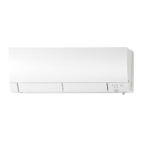
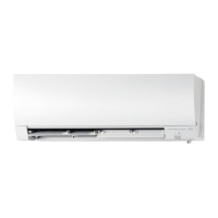
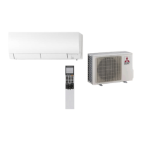
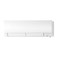
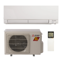
Identifies and describes the various parts of the indoor unit and its accessories.
Lists detailed electrical, airflow, sound, and fan speed specifications for different models.
Provides graphical data on sound pressure levels across different frequencies for various fan speeds.
Displays physical dimensions, piping sizes, and installation details of the indoor unit.
Illustrates the electrical connections and component layout for different indoor unit models.
Shows the flow of refrigerant and the location of key thermistors within the system.
Shortens compressor start-up time for service purposes.
Assigns a specific remote controller to a particular indoor unit.
Configures unit operation based on its installed location.
Allows unit to resume operation with previous settings after power interruption.
Explains the buttons and display of the wireless remote control unit.
Describes the meaning of the operation indicator lamp on the indoor unit.
Details operation, frost prevention, and fan speed control in Cool mode.
Explains operation, frost prevention, and fan speed control in Dry mode.
Describes the function of the Fan mode, operating the indoor fan only.
Covers operation, cold air prevention, and defrosting in Heat mode.
Explains automatic switching between Cool and Heat modes.
Details automatic adjustment of horizontal vanes for optimal air distribution.
Explains the drive, positioning, and modes for horizontal vane control.
Describes the drive, positioning, and swing modes for the vertical vane control.
Covers setting current time, ON/OFF timers, and program timer functions.
Guides on setting the current time on the remote controller for timer accuracy.
Explains how to cancel the set ON or OFF timers.
Illustrates combining ON and OFF timers for scheduled operation.
Details setting up weekly timer schedules for individual days or the entire week.
Provides steps for entering the weekly timer setting mode and configuring daily schedules.
Explains how to view the programmed weekly timer settings.
Details the i-see sensor function for temperature control based on occupancy.
Describes the energy-saving function that activates when no one is in the room.
Explains how to direct airflow towards or away from occupants for comfort.
Simulates natural wind airflow for enhanced comfort.
Describes the function that reduces airborne fungi, viruses, and allergens.
Allows saving and recalling custom settings for temperature, fan speed, and airflow direction.
Guides on setting and saving preferred operational parameters.
Explains how to exit the i-save operation mode.
Details using the emergency operation switch for testing or when remote fails.
Protects the compressor by preventing immediate restarts after shutdown.
Lists critical safety precautions and checks before starting troubleshooting.
Emphasizes checking power supply and wiring connections before proceeding.
Outlines essential safety measures during servicing, like power disconnection.
Describes general steps for diagnosing abnormalities, including checking indicator lamps.
Guides on replacing remote controller batteries to resolve operational issues.
Explains how to retrieve and interpret stored error codes for diagnosis.
Provides a visual guide for using the failure mode recall function.
Details the steps to exit the failure mode recall function properly.
Describes how to clear stored error codes after repairs are completed.
Outlines the procedure to verify the functionality of the air purifying system.
Correlates operation indicator patterns with specific faults and remedies.
Lists specific failure modes for indoor units based on POWER lamp blinking patterns.
Details failure modes related to the air purifying power control and electrode.
Describes how to check the i-see sensor for proper contact and data loading.
A flowchart guiding troubleshooting based on unit operating status and indicator lamps.
Continues the table correlating operation indicator patterns with specific faults and remedies.
Specifies resistance values and checks for key components like thermistors and motors.
A flowchart for diagnosing indoor fan motor issues and related component checks.
A flowchart for diagnosing issues related to the remote controller and indoor P.C. board.
A flowchart for checking the indoor P.C. board and fan motor for electrical issues.
A flowchart for identifying and resolving miswiring or communication errors.
Continues the flowchart for miswiring and serial signal error diagnosis.
Explains LED indications on outdoor display boards for communication status.
A flowchart for diagnosing issues with the air purifying system's power.
Discusses potential electromagnetic interference issues and troubleshooting steps.
Provides detailed diagrams and voltage test points for various electronic boards.
Guides on disassembling the unit, starting with panel removal.
Specifies the models covered by the disassembly instructions.
Explains the steps to detach the electrical box containing various components.
Provides instructions for removing key internal electronic boards and assemblies.
Details the procedure for removing the nozzle assembly and vane motors.
Guides on detaching and removing the vertical and horizontal vane motors.
Explains the steps to remove the air purifying device and its support.
Details the process for removing the fan motor, thermistor, and airflow fan.