2013 M-Series - MSZ-GE Heat Pump Systems (June 2013)
MSZ-GE-1
© 2013 Mitsubishi Electric US, Inc.
Due to continuing improvement, above specication may be subject to change without notice.
M-SERIES SINGLE ZONE SYSTEMS
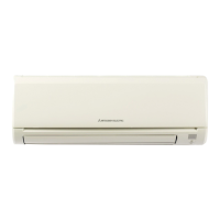
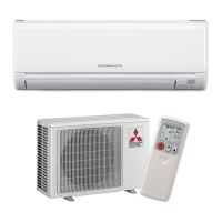
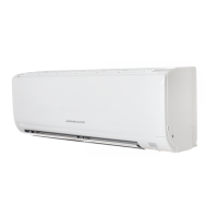
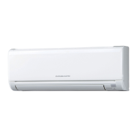
MSZ-GE WALL-MOUNT HEAT PUMP SYSTEMS
1. INDOOR UNITS ................................................................................................................................................MSZ-GE-2
2. OUTDOOR UNITS ............................................................................................................................................MSZ-GE-3
3. SYSTEM............................................................................................................................................................MSZ-GE-4
3-1.Specications .................................................................................................................................. MSZ-GE-4
3-2.ExternalDimensions ..................................................................................................................... MSZ-GE-11
3-3.CenterofGravity ........................................................................................................................... MSZ-GE-16
3-4.ElectricalWiringDiagrams ............................................................................................................ MSZ-GE-17
3-5.RefrigerantSystemDiagrams ....................................................................................................... MSZ-GE-23
3-6.CapacityCorrectionCurvebyTemperature .................................................................................. MSZ-GE-28
3-7.CapacityCorrectionTablebyTemperature ...................................................................................MSZ-GE-30
3-8.CapacityCorrectionCurvebyRefrigerantPipingLength .............................................................MSZ-GE-34
3-9.CapacityCorrectionTablebyRefrigerantPipingLength ..............................................................MSZ-GE-35
3-10.ChargeCalculations ....................................................................................................................MSZ-GE-37
3-11.AirFlowData ............................................................................................................................... MSZ-GE-38
3-12.SoundPressureLevels ...............................................................................................................MSZ-GE-39
3-13.StandardOperationRange .........................................................................................................MSZ-GE-49
3-14.Accessories ................................................................................................................................. MSZ-GE-50