EasyManua.ls Logo

Mitsubishi Electric MSZ-GE35VA2-A1 User Manual

Mitsubishi Electric MSZ-GE35VA2-A1
54 pages
To Next Page IconTo Next Page
Page #1 background imageLoading...
Page #1 background image
CONTENTS
1. TECHNICAL CHANGES ··································· 2
2. PART NAMES AND FUNCTIONS ····················· 3
3. SPECIFICATION ················································ 5
4. NOISE CRITERIA CURVES ······························ 9
5. OUTLINES AND DIMENSIONS ·······················11
6. WIRING DIAGRAM ·········································· 12
7. REFRIGERANT SYSTEM DIAGRAM ············· 14
8. SERVICE FUNCTIONS ··································· 15
9. MICROPROCESSOR CONTROL ··················· 17
10. TROUBLESHOOTING ····································· 25
11. DISASSEMBLY INSTRUCTIONS ···················· 45
SPLIT-TYPE AIR CONDITIONERS
SERVICE MANUAL
INDOOR UNIT
PARTS CATALOG (OBB531)
NOTE:
RoHS compliant products have <G> mark on the spec name plate.
Models
MSZ-GE22VA
-
A1
MSZ-GE50VA
-
A1
MSZ-GE22VAD
-
A1
MSZ-GE50VA2
-
A1
MSZ-GE25VA
-
A1
MSZ-GE50VAD
-
A1
MSZ-GE25VAD
-
A1
MSZ-GE60VA
-
A1
MSZ-GE33VA
-
A1
MSZ-GE60VAD
-
A1
MSZ-GE35VA
-
A1
MSZ-GE71VA
-
A1
MSZ-GE35VA2
-
A1
MSZ-GE71VAD
-
A1
MSZ-GE35VAD
-
A1
MSZ-GE80VA
-
A1
MSZ-GE42VA
-
A1
MSZ-GE80VA2
-
A1
MSZ-GE42VAD
-
A1
MSZ-GE80VAD
-
A1
No. OBH531
REVISED EDITION-E
Please void OBH531 REVISED EDITION-D.
MSZ-GE22VA
MSZ-GE22VAD
MSZ-GE25VA
MSZ-GE25VAD
MSZ-GE33VA
MSZ-GE35VA
MSZ-GE35VA2
MSZ-GE35VAD
MSZ-GE42VA
MSZ-GE42VAD
MSZ-GE50VA
MSZ-GE50VA2
MSZ-GE50VAD
Revision E:
MSZ-GE22VAD-
A1
has been added.
Outdoor unit service manual
MUZ-GE·VA Series (OBH532)
MXZ-A·VA Series (OB447)
MXZ-8A140A (OC316)
MXZ-B•VA (OBH567)
Question and Answer IconNeed help?

Do you have a question about the Mitsubishi Electric MSZ-GE35VA2-A1 and is the answer not in the manual?

Mitsubishi Electric MSZ-GE35VA2-A1 Specifications

General IconGeneral
BrandMitsubishi Electric
ModelMSZ-GE35VA2-A1
CategoryAir Conditioner
LanguageEnglish

Summary

Technical Changes Overview

New Model and Component Updates

Details new model additions and component modifications like P.C. boards and V.A clamps.

Part Names and Functions

Indoor Unit Component Identification

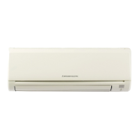
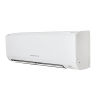
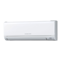
Visual guide with diagrams identifying all parts of the indoor unit.

Specifications

Electrical, Airflow, and Sound Specifications

Detailed electrical data, airflow performance, and sound pressure levels.

Fan Speed and Electric Parts Specifications

Fan speed ratings and specifications for main electric components.

Noise Criteria Curves

Model-Specific Noise Performance

Graphs detailing octave band sound pressure levels for various models and conditions.

Outlines and Dimensions

Physical Dimensions and Installation Layout

Diagrams showing physical dimensions and installation considerations for indoor units.

Wiring Diagrams

Indoor Unit Electrical Connections

Schematic diagrams illustrating the internal wiring of indoor units.

Refrigerant System Diagrams

Refrigerant Piping and Flow

Diagrams illustrating refrigerant pipe sizes and flow direction for cooling/heating.

Service Functions

Timer Short Mode and PC Board Modification

Instructions for shortening timer settings and modifying PC boards for individual operation.

Auto Restart Function

Details on the automatic restart feature and its disabling procedure.

Microprocessor Control

Wireless Remote Controller Operation

Functions and operation of the wireless remote controller.

Indoor Unit Operation Modes and Display

Explanation of operation indicator, COOL, DRY, HEAT, FAN, and AUTO modes.

Timer, Vane, and Special Functions

Details on auto vane, timer, weekly timer, i-save, and emergency operations.

Troubleshooting

General Cautions and Failure Recall

Preparatory steps, cautions, and how to recall memorized abnormal conditions.

Diagnostic Flows, Tables, and Component Checks

Flowcharts, check tables, and criteria for diagnosing unit malfunctions.

Specific Error Checks

Troubleshooting for fan motor errors, controller issues, and wiring faults.

Installation and Noise Troubleshooting

Diagnosing horizontal vane installation and electromagnetic noise issues.

Disassembly Instructions

Panel and Basic Component Removal

Procedures for removing front panel, terminals, and basic internal components.

Motor, Sensor, and Fan Removal

Steps for removing motors, sensors, fan, and heat exchanger assemblies.

Disassembly for Larger Models

Specific disassembly procedures for larger indoor unit models.

Related product manuals