Do you have a question about the Mitsubishi Electric MSZ-GE50VA-A1 and is the answer not in the manual?
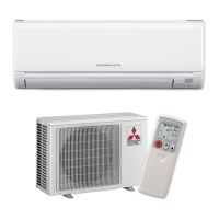
| Cooling Capacity | 5.0 kW |
|---|---|
| Power Supply | 220-240 V, 50 Hz |
| Weight (Outdoor Unit) | 35 kg |
| Outdoor Unit Weight | 35 kg |
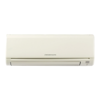
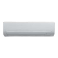
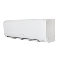
| Type | Split System |
| Outdoor Unit Dimensions (HxWxD) | 550 x 780 x 285 mm |
| Power Source | 220-240V |
Shortens timer setting time for service operations.
Modifies P.C. boards for multi-unit operation.
Manages automatic unit restart after power interruption.
Details the operation procedure for cooling mode.
Details the operation procedure for dry mode.
Details the operation procedure for heat mode.
Details operation procedure for fan-only mode.
Explains automatic switching between COOL and HEAT modes.
Controls horizontal vane movement and modes.
Details how to set and release timers.
Allows setting weekly ON/OFF timers for operations.
Allows saving and recalling custom settings.
Provides procedures for emergency and test operations.
Explains the compressor protection time delay.
Safety and general precautions before troubleshooting.
Recalls and displays memorized abnormal conditions.
Provides a flowchart for diagnosing issues.
Lists symptoms, conditions, and remedies for faults.
Step-by-step guide for fan motor issues.
Shows test points and voltages for diagnostics.
Checks remote control and indoor PC board for issues.
Diagnoses issues with PC boards and fan motor.
Guides on diagnosing miswiring and serial signal errors.
Checks correct installation of the horizontal vane.
Addresses issues with electromagnetic noise interference.
Step-by-step guide for removing the front panel.
Procedures for removing the main control board and thermistor.
Steps to remove power board, terminal board, and electrical box.
Instructions for removing the nozzle assembly.
Steps for removing the vertical vane motor.
Steps for removing the horizontal vane motor.
Guide to remove water cut, fan motor, thermistor, and fan.
Steps to remove control board, monitor board, terminal board.
Procedures for removing the indoor electrical box.
Instructions for removing the nozzle assembly.
Steps for removing the vertical vane motor.
Steps for removing the horizontal vane motor.