EasyManua.ls Logo

Mitsubishi Electric MSZ-GE71VAD-A1 User Manual

Mitsubishi Electric MSZ-GE71VAD-A1
54 pages
To Next Page IconTo Next Page
Page #1 background imageLoading...
Page #1 background image
CONTENTS
1. TECHNICAL CHANGES ··································· 2
2. PART NAMES AND FUNCTIONS ····················· 3
3. SPECIFICATION ················································ 5
4. NOISE CRITERIA CURVES ······························ 9
5. OUTLINES AND DIMENSIONS ·······················11
6. WIRING DIAGRAM ·········································· 12
7. REFRIGERANT SYSTEM DIAGRAM ············· 14
8. SERVICE FUNCTIONS ··································· 15
9. MICROPROCESSOR CONTROL ··················· 17
10. TROUBLESHOOTING ····································· 25
11. DISASSEMBLY INSTRUCTIONS ···················· 45
SPLIT-TYPE AIR CONDITIONERS
SERVICE MANUAL
INDOOR UNIT
PARTS CATALOG (OBB531)
NOTE:
RoHS compliant products have <G> mark on the spec name plate.
Models
MSZ-GE22VA
-
A1
MSZ-GE50VA
-
A1
MSZ-GE22VAD
-
A1
MSZ-GE50VA2
-
A1
MSZ-GE25VA
-
A1
MSZ-GE50VAD
-
A1
MSZ-GE25VAD
-
A1
MSZ-GE60VA
-
A1
MSZ-GE33VA
-
A1
MSZ-GE60VAD
-
A1
MSZ-GE35VA
-
A1
MSZ-GE71VA
-
A1
MSZ-GE35VA2
-
A1
MSZ-GE71VAD
-
A1
MSZ-GE35VAD
-
A1
MSZ-GE80VA
-
A1
MSZ-GE42VA
-
A1
MSZ-GE80VA2
-
A1
MSZ-GE42VAD
-
A1
MSZ-GE80VAD
-
A1
No. OBH531
REVISED EDITION-E
Please void OBH531 REVISED EDITION-D.
MSZ-GE22VA
MSZ-GE22VAD
MSZ-GE25VA
MSZ-GE25VAD
MSZ-GE33VA
MSZ-GE35VA
MSZ-GE35VA2
MSZ-GE35VAD
MSZ-GE42VA
MSZ-GE42VAD
MSZ-GE50VA
MSZ-GE50VA2
MSZ-GE50VAD
Revision E:
MSZ-GE22VAD-
A1
has been added.
Outdoor unit service manual
MUZ-GE·VA Series (OBH532)
MXZ-A·VA Series (OB447)
MXZ-8A140A (OC316)
MXZ-B•VA (OBH567)
Question and Answer IconNeed help?

Do you have a question about the Mitsubishi Electric MSZ-GE71VAD-A1 and is the answer not in the manual?
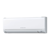
Mitsubishi Electric MSZ-GE71VAD-A1 Specifications

General IconGeneral
TypeSplit System
Cooling Capacity7.1 kW
Heating Capacity8.0 kW
Power Supply220-240 V, 50 Hz
RefrigerantR410A
Weight (Outdoor Unit)55 kg
Outdoor Unit Weight55 kg
Operating Temperature Range (Heating)-15 to 24°C
Operating Temperature Range (Cooling)-10°C to 46°C

Summary

1 TECHNICAL CHANGES

2 PART NAMES AND FUNCTIONS

ACCESSORIES

3 SPECIFICATION

Specifications and Rated Conditions of Main Electric Parts

Details electrical ratings and conditions for primary unit components.

4 NOISE CRITERIA CURVES

5 OUTLINES AND DIMENSIONS

6 WIRING DIAGRAM

7 REFRIGERANT SYSTEM DIAGRAM

8 SERVICE FUNCTIONS

Timer Short Mode

Shortens compressor start-up time for service operations.

PC Board Modification for Individual Operation

Details modifications for using multiple remote controllers with indoor units.

Auto Restart Function

Enables the unit to resume operation with previous settings after a power interruption.

9 MICROPROCESSOR CONTROL

Wireless Remote Controller

Details the functions and operation of the remote control unit.

Indoor Unit Display Section

Describes the indicators and their meaning on the indoor unit.

Cool Operation

Explains the procedures and features of the cooling mode.

Dry Operation

Details the operation and modes for dehumidification.

Heat Operation

Describes the procedures and features of the heating mode.

Fan Operation

Explains the operation of the unit in fan-only mode.

Auto Changeover Operation

Covers automatic switching between cooling and heating modes.

Auto Vane Operation

Describes the automatic adjustment of air direction louvers.

Timer Operation

Explains how to set and use the unit's timer functions.

Weekly Timer Operation

Details setting programmable timers for daily and weekly schedules.

i-Save Operation

Covers saving and recalling preferred operating settings.

Emergency/Test Operation

Explains manual operation modes for testing and emergencies.

3-Minute Time Delay Operation

Ensures compressor protection by delaying restart after shutdown.

10 TROUBLESHOOTING

Cautions on Troubleshooting

Highlights safety precautions and initial checks before troubleshooting.

How to Install the Horizontal Vane

Provides steps for correctly installing the horizontal vane component.

Failure Mode Recall Function

Describes how to retrieve and interpret stored error codes from the unit.

Instruction of Troubleshooting

Offers a systematic approach to diagnosing unit problems.

Troubleshooting Check Table

Lists common faults, symptoms, conditions, and remedies.

Trouble Criterion of Main Parts

Details resistance values and checks for key electronic components.

Troubleshooting Flow

Presents decision trees for diagnosing specific operational errors.

Check Remote Controller and Indoor PC Board

Guides troubleshooting for issues related to the remote and control boards.

Check Indoor PC Board and Fan Motor

Provides steps to diagnose problems with the indoor control board and fan motor.

Check Miswiring and Serial Signal Error

Details procedures for identifying and correcting wiring and communication faults.

Check Horizontal Vane Installation

Guides on verifying the correct installation of the horizontal vane.

Electromagnetic Noise Interference

Explains how to identify and mitigate interference with external devices.

Test Point Diagram and Voltage

Shows test points and voltage readings for diagnosing electronic issues.

11 DISASSEMBLY INSTRUCTIONS

Removing the Panel

Details the process for safely removing the front panel of the unit.

Removing the Indoor Electronic Control PC Board and Thermistor

Guides the removal of the main control board and temperature sensors.

Removing Indoor Power PC Board, Terminal PC Board, and Electrical Box

Details the removal of power supply and terminal components.

Removing the Nozzle Assembly

Provides steps for detaching the air outlet nozzle assembly.

Removing the Vertical Vane Motor Unit

Guides the removal of the vertical vane motor assembly.

Removing the Horizontal Vane Motor

Details the process for removing the horizontal vane motor.

Removing Water Cut, Fan Motor, Coil Thermistor, and Line Flow Fan

Describes removal of key internal components like fan and motor.

Removing the Panel (Larger Models)

Details the process for safely removing the front panel of larger unit models.

Removing Indoor Control/Monitor Boards and Electrical Box (Larger Models)

Guides removal of boards and electrical box for larger units.

Removing Nozzle Assembly and Vane Motors (Larger Models)

Details removal of nozzle assembly and vane motors for larger units.

Removing Water Cut, Fan Motor, Thermistor, and Fan (Larger Models)

Describes removal of internal components for larger units.

Related product manuals