EasyManua.ls Logo

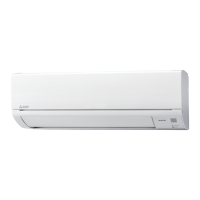
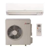
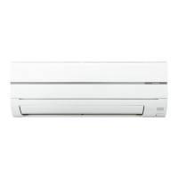
Mitsubishi Electric MSZ-WR12NA-U2 User Manual

Mitsubishi Electric MSZ-WR12NA-U2
40 pages
To Next Page IconTo Next Page
Page #1 background imageLoading...
Page #1 background image
Outdoor unit service manual
MUZ-WRNA Series (OBH819)
PARTS CATALOG (OBB818)
MSZ-WR24NA
INDOOR UNIT
SERVICE MANUAL
INDOOR UNIT
Models
MSZ-WR09NA
-
U1
,
U2
MSZ-WR12NA
-
U1
,
U2
MSZ-WR18NA
-
U1
MSZ-WR24NA
-
U1
CONTENTS
1. TECHNICAL CHANGES
· ·······························
2
2. PART NAMES AND FUNCTIONS ··················3
3. SPECIFICATION ········································5
4. OUTLINES AND DIMENSIONS ·····················7
5. WIRING DIAGRAM ·····································8
6. REFRIGERANT SYSTEM DIAGRAM ···········10
7. SERVICE FUNCTIONS ······························11
8. MICROPROCESSOR CONTROL ················13
9. TROUBLESHOOTING ······························· 17
10. DISASSEMBLY INSTRUCTIONS ·················32
No. OBH818
REVISED EDITION-C
OBH818 REVISED EDITION-B is void.
Revision C:
• MSZ-WR09/12NA -
U2
have been added.
Question and Answer IconNeed help?

Do you have a question about the Mitsubishi Electric MSZ-WR12NA-U2 and is the answer not in the manual?

Mitsubishi Electric MSZ-WR12NA-U2 Specifications

General IconGeneral
BrandMitsubishi Electric
ModelMSZ-WR12NA-U2
CategoryAir Conditioner
LanguageEnglish

Summary

SPECIFICATION

WIRING DIAGRAM

REFRIGERANT SYSTEM DIAGRAM

SERVICE FUNCTIONS

Timer Mode and Remote Controller Setup

Instructions for timer short mode and modifying remote controller for individual unit operation.

Auto Restart Function Operation

Details on the auto restart function and how to disable it by modifying jumper wires.

MICROPROCESSOR CONTROL

Emergency and Test Operation Procedures

Guide to using the emergency operation switch for testing and service diagnostics.

TROUBLESHOOTING

General Troubleshooting Precautions

Safety guidelines and initial checks before performing troubleshooting.

Failure Mode Recall Function Overview

Introduction to the function that allows recalling memorized failure details.

Failure Mode Recall Function Flowchart

Detailed flowchart for initiating and interpreting the failure mode recall function.

Indoor Unit Failure Mode Recall Table

Table detailing indoor unit failure modes, conditions, and remedies based on indicator lamp blinking.

Comprehensive Troubleshooting Flow

A detailed flowchart for diagnosing various operational issues by checking unit status and signals.

Troubleshooting Check Table

A table detailing specific indoor unit faults, symptoms, conditions, and recommended remedies.

Troubleshooting Criteria for Main Parts

Guidelines for checking resistance and function of key components like thermistors and motors.

Indoor Fan Motor Troubleshooting Flow

Step-by-step diagnostic procedure for issues related to the indoor fan motor.

Remote Controller and Indoor Unit Communication Check

Procedures to verify remote controller operation and its communication with the indoor unit.

Indoor P.C. Board and Fan Motor Diagnostic Flow

Diagnostic steps for indoor P.C. boards and fan motor, involving resistance and voltage checks.

Miswiring and Serial Signal Diagnosis (WR09/12NA)

Detailed steps for checking miswiring and serial signal errors for MSZ-WR09/12NA models.

Miswiring and Serial Signal Diagnosis (WR18/24NA)

Detailed steps for checking miswiring and serial signal errors for MSZ-WR18/24NA models.
TEST POINT DIAGRAM AND VOLTAGE

DISASSEMBLY INSTRUCTIONS

Related product manuals