Do you have a question about the Mitsubishi Electric MSZ-WR24NA-U1 and is the answer not in the manual?
| Category | Air Conditioner |
|---|---|
| Brand | Mitsubishi Electric |
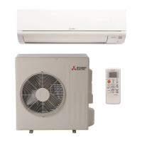
| Model | MSZ-WR24NA-U1 |
| Type | Split System |
| Cooling Capacity | 24000 BTU/h |
| Seasonal Energy Efficiency Ratio (SEER) | 20.5 |
| Refrigerant | R410A |
| HSPF (Heating) | 10.0 |
| Operating Temperature (Cooling) | 14°F to 115°F |
| Power Supply | 208-230V, 60Hz |
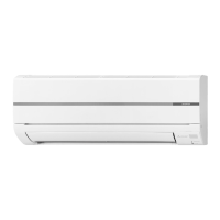
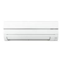
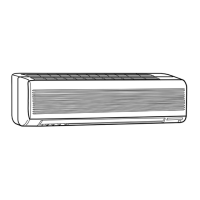
Identifies and describes the various parts of the indoor air conditioning unit.
Details technical specifications like power, airflow, sound level, and dimensions for different models.
Illustrates the internal wiring schematic for indoor unit electronic components and connections.
Depicts the refrigerant flow path and the location of associated thermistors within the indoor unit.
Explains the functions, buttons, and operation of the wireless remote controller.
Procedures for activating emergency or test operations using the unit's switch.
Important safety and preparatory steps before commencing any troubleshooting.
Method for recalling and displaying memorized failure codes from the unit's memory.
A structured guide for diagnosing common unit malfunctions and issues.
A table correlating indicator patterns with failure points and recommended remedies.
Guide to identifying and rectifying wiring errors and communication signal issues.
Illustrates test points and required voltage measurements for electronic board diagnostics.