EasyManua.ls Logo

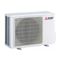
Mitsubishi Electric MUH-GA35VB- E3 User Manual

Mitsubishi Electric MUH-GA35VB- E3
36 pages
To Next Page IconTo Next Page
Page #1 background imageLoading...
Page #1 background image
CONTENTS
1. TECHNICAL CHANGES ····································2
2. PART NAMES AND FUNCTIONS······················3
3. SPECIFICATION·················································3
4. NOISE CRITERIA CURVES·······························5
5. OUTLINES AND DIMENSIONS ·························6
6. WIRING DIAGRAM ············································7
7. REFRIGERANT SYSTEM DIAGRAM················8
8. PERFORMANCE CURVES································9
9. ACTUATOR CONTROL····································19
10. SERVICE FUNCTIONS·····································20
11. TROUBLESHOOTING······································20
12. DISASSEMBLY INSTRUCTIONS·····················27
13. PARTS LIST······················································30
14. RoHS PARTS LIST···········································32
HFC
utilized
R410A
SPLIT-TYPE, HEAT PUMP AIR CONDITIONERS
MUH-GA20VB
MUH-GA25VB
MUH-GA35VB
Wireless type
Models
MUH-GA20VB-
MUH-GA20VB-
MUH-GA25VB-
MUH-GA25VB-
MUH-GA35VB-
MUH-GA35VB-
E3
E1
E2
E1
E2
E1
SERVICE MANUAL
OUTDOOR UNIT
Indoor unit service manual
MSC-GAVB Series (OB385)
MSC-CAVB Series (OB393)
MSC-CBVB Series (OB439)
No. OB387
REVISED EDITION-B
Please void OB387 REVISED EDITION-A.
Revision B:
MUH-GA35VB - has been added.
E3
NOTE:
• This service manual describes technical data of outdoor units.
• RoHS compliant products have <G> mark on the spec name plate.
For servicing of RoHS compliant products, refer to the RoHS Parts List.
OB387B-1.qxp 07.5.23 2:47 PM Page 1

Questions and Answers:

Mitsubishi Electric MUH-GA35VB- E3 Specifications

General IconGeneral
BrandMitsubishi Electric
ModelMUH-GA35VB- E3
CategoryAir Conditioner
LanguageEnglish

Summary

1 TECHNICAL CHANGES

2 PART NAMES AND FUNCTIONS

3 SPECIFICATION

4 NOISE CRITERIA CURVES

5 OUTLINES AND DIMENSIONS

6 WIRING DIAGRAM

7 REFRIGERANT SYSTEM DIAGRAM

8 PERFORMANCE CURVES

GUARANTEED VOLTAGE

Specifies the acceptable voltage range for operation.

AIR FLOW

Instructions for setting the air flow to maximum.

MAIN READINGS

Defines the key parameters for performance data readings.

8-2 OUTDOOR LOW PRESSURE AND OUTDOOR UNIT CURRENT COOL operation

HEAT operation

PERFORMANCE DATA COOL operation (230V)

9 ACTUATOR CONTROL

R.V. coil control

Describes the control states for the R.V. coil in different modes.

NOTE

Information about the 4-way valve reversing timing.

10 SERVICE FUNCTIONS

10-1. COMPULSORY DEFROSTING MODE FOR SERVICE

Procedure to force defrosting regardless of normal conditions.

10-2. CHANGE IN DEFROST SETTING

Instructions for modifying defrost interval and temperature settings.

11 TROUBLESHOOTING

11-1. Cautions on troubleshooting

Important warnings and precautions before starting troubleshooting.

11-2. Instruction of troubleshooting

Outdoor unit does not operate.

Troubleshooting steps when the outdoor unit fails to operate.

Outdoor unit does not operate normally.

Steps to diagnose and fix abnormal outdoor unit operation.

Indoor unit does not receive signal from remote controller.

Troubleshooting for communication issues with the remote controller.

OPERATION INDICATOR lamp on the indoor unit is flashing on and off.

Diagnosing and resolving issues indicated by the indoor unit's error lamp.

11-3. Trouble criterion of main parts

11-4. Troubleshooting flow

Compressor and/or outdoor fan motor doesn't operate.

Flowchart for diagnosing compressor/fan motor operational failures.

Compressor and/or outdoor fan motor doesn't stop.

Troubleshooting flow for units that fail to stop operation.

Unit operates COOL mode even if it is set to HEAT mode.

Troubleshooting steps for incorrect mode operation (COOL instead of HEAT).

Unit operates HEAT mode even if it is set to COOL mode.

Troubleshooting steps for incorrect mode operation (HEAT instead of COOL).

When OPERATION INDICATOR lamp flashes 0.5-second intervals. Outdoor unit does not operate.

How to check mis-wiring and serial signal error

Procedure for diagnosing and correcting wiring and signal errors.

When OPERATION INDICATOR lamp flashes 6-time. Thermistors in the outdoor unit are abnormal.

Check of outdoor thermistor

Steps to check the outdoor thermistor's functionality and resistance.

11-5. Test point diagram and voltage

12 DISASSEMBLY INSTRUCTIONS

<"Terminal with locking mechanism" Detaching points>

Explains how to detach terminals with locking mechanisms.

OPERATING PROCEDURE

Step-by-step guide for removing the outdoor unit cabinet.

Removing the deicer P.C. board

Procedure for removing the deicer P.C. board.

Removing the propeller and the outdoor fan motor

Steps to safely remove the propeller and fan motor assembly.

Removing the compressor

Detailed steps for safely removing the compressor from the unit.

13 PARTS LIST (non-RoHS compliant)

13-1. OUTDOOR UNIT

List of structural, electrical, and functional parts for outdoor units.

14 RoHS PARTS LIST (RoHS compliant)

14-1. OUTDOOR UNIT

List of structural, electrical, and functional parts for outdoor units compliant with RoHS.

Related product manuals