EasyManua.ls Logo

Mitsubishi Electric MUM18NW User Manual

Mitsubishi Electric MUM18NW
21 pages
To Next Page IconTo Next Page
Page #1 background imageLoading...
Page #1 background image
TECHNICAL & SERVICE MANUAL
DUCTLESS SPLIT-TYPE AIR CONDITIONERS
CONTENTS
1. FEATURES·························································2
2. TECHNICAL CHANGES ····································3
3. PART NAMES AND FUNCTIONS······················3
4. SPECIFICATIONS ··············································4
5. DATA···································································5
6. OUTLINES AND DIMENSIONS ·························9
7. WIRING DIAGRAM ··········································10
8. REFRIGERANT SYSTEM DIAGRAM ··············11
9. TROUBLESHOOTING······································12
10. DISASSEMBLY INSTRUCTIONS·····················14
11. PARTS LIST······················································17
12. OPTIONAL PARTS···········································18
Wireless type
Models
MS09NW2 •MUM18NW
No.OB202
The Slim Line.
From Mitsubishi Electric.
L
I
S
T
E
D
R
NOTE :For parts list, please refer to the following manuals.
MS09NW OB192
MUM18NW
LCD Wireless
remote controller
LCD Wireless
remote controller
MS09NW MS09NW
OB202-1.qxp 26/9/97 11:07 AM Page 1
Question and Answer IconNeed help?

Do you have a question about the Mitsubishi Electric MUM18NW and is the answer not in the manual?
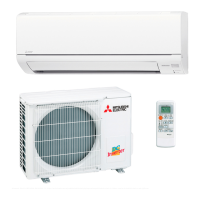
Mitsubishi Electric MUM18NW Specifications

General IconGeneral
BrandMitsubishi Electric
ModelMUM18NW
CategoryAir Conditioner
LanguageEnglish

Summary

FEATURES

SPACE-SAVING LAYOUT

Describes the compact installation benefit.

FLEXIBLE INSTALLATION OF INDOOR UNITS

Highlights the freedom in placing indoor units.

AUTO-RESTART FUNCTION

Explains the automatic restart capability after power interruption.

TECHNICAL CHANGES

PART NAMES AND FUNCTIONS

SPECIFICATIONS

DATA

PERFORMANCE DATA (ONE INDOOR UNIT WITH ONE OUTDOOR UNIT)

Provides performance data for single indoor/outdoor unit configuration.

COOLING CAPACITY CORRECTIONS

Details adjustments to cooling capacity based on piping length.

PERFORMANCE CURVES (ONE INDOOR UNIT WITH ONE OUTDOOR UNIT)

Displays performance curves for cooling capacity and power consumption.

CONDENSING AND SUCTION PRESSURE

Presents graphs for condensing and suction pressure based on ambient conditions.

STANDARD OPERATION DATA

POWER SUPPLY

Details electrical power supply requirements and connections for the units.

OPERATING RANGE

OPERATING RANGE POWER SUPPLY

Specifies power supply voltage ranges for indoor and outdoor units.

OPERATION CONDITIONS

Outlines operating conditions including temperature and humidity.

ADDITIONAL REFRIGERANT CHARGE

Provides guidelines for additional refrigerant charge based on piping length.

MAX. REFRIGERANT PIPING LENGTH AND HEIGHT DIFFERENCE

Specifies maximum allowed piping length and height difference.

PIPING PREPARATION

Details pipe specifications and installation notes for refrigerant lines.

OUTLINES AND DIMENSIONS

WIRING DIAGRAM

REFRIGERANT SYSTEM DIAGRAM

TROUBLESHOOTING

CAUTIONS ON TROUBLESHOOTING

Important safety and handling precautions before starting troubleshooting.

TROUBLESHOOTING CRITERIA FOR MAIN PARTS

Criteria and methods for checking the normal/abnormal status of major components.

DISASSEMBLY INSTRUCTIONS

REMOVING THE CABINET

Step-by-step guide to remove the outer cabinet of the unit.

REMOVING THE PROPELLER

Instructions for safely removing the fan propeller.

REMOVING THE OUTDOOR FAN MOTOR

Guide to detach the outdoor fan motor.

REMOVING THE COMPRESSOR

Procedures for safely removing the compressor unit.

PARTS LIST

OPTIONAL PARTS

REFRIGERANT PIPES

Details specifications for optional refrigerant extension pipes.

Related product manuals