1. BEFORE INSTALLATION
1-1. THE FOLLOWING SHOULD ALWAYS BE OBSERVED FOR SAFETY
• Be sure to read these safety precautions and instructions.
%HVXUHWRREVHUYHWKHZDUQLQJVDQGFDXWLRQVVSHFL¿HGKHUH
• After reading this manual, be sure to store it with the OPERATING INSTRUCTIONS for future reference.
• Please report to your supply authority or obtain their consent before connecting this equipment to the power supply system.
DG79A04VH01
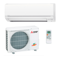
SPLIT-TYPE AIR CONDITIONERS
INSTALLATION MANUAL
ENGLISH
Required Tools for Installation
Phillips screwdriver
Level
Scale
Utility knife or scissors
3 in. (75 mm) hole saw
Torque wrench
Wrench (or spanner)
5/32 in. (4 mm) hexagonal
wrench
Flare tool for R410A
Gauge manifold for R410A
Vacuum pump for R410A
Charge hose for R410A
Pipe cutter with reamer
MSZ-GS06/09/12/15NA
MSY-GS09/12/15NA
When installing multi units, refer to the
installation manual of the multi unit for
outdoor unit installation.
■ Do not install the unit by yourself (user).
,PSURSHURULQFRPSOHWHLQVWDOODWLRQFRXOGFDXVH¿UHHOHFWULFVKRFNLQMXU\GXHWR
WKHXQLWIDOOLQJRUZDWHUOHDNDJH&RQVXOWDTXDOL¿HGLQVWDOOHURUWKHGHDOHUIURP
whom you purchased the unit.
■ Follow the instructions detailed in the installation manual.
,QFRPSOHWHLQVWDOODWLRQFRXOGFDXVH¿UHRUHOHFWULFVKRFNLQMXU\GXHWRWKHXQLWIDOO-
ing, or leakage of water.
■ When installing the unit, use appropriate protective equipment and tools for
safety.
Failure to do so could cause injury.
■ Install the unit securely in a place that can bear the weight of the unit.
If the installation location cannot bear the weight of the unit, the unit could fall
causing injury.
■ Do not alter the unit.
,WPD\FDXVH¿UHHOHFWULFVKRFNLQMXU\RUZDWHUOHDNDJH
■ Perform electrical work according to the installation manual and be sure to use
an exclusive circuit. Do not connect other electrical appliances to the circuit.
,IWKHFDSDFLW\RIWKHSRZHUFLUFXLWLVLQVXI¿FLHQWRUWKHUHLVLQFRPSOHWHHOHFWULFDO
ZRUNLWFRXOGUHVXOWLQD¿UHRUDQHOHFWULFVKRFN
■ Ground the unit correctly.
Do not connect the ground wire to a gas pipe, water pipe, lightning rod or tel-
ephone ground. Defective grounding could cause electric shock.
■ Do not damage the wires.
'DPDJHGZLUHVFRXOGFDXVH¿UH
■ Be sure to shut off the main power when setting up the indoor P.C. board or
wiring.
Failure to do so could cause electric shock.
■ 8VHWKHVSHFL¿HGZLUHVWRVHFXUHO\FRQQHFWWKHLQGRRUDQGRXWGRRUXQLWV$W-
WDFKWKHZLUHV¿UPO\WRDYRLGDSSO\LQJVWUHVVWRWKHWHUPLQDOEORFN
,PSURSHUFRQQHFWLRQFRXOGFDXVH¿UH
■ 'RQRWLQVWDOOWKHXQLWLQDSODFHZKHUHÀDPPDEOHJDVPD\OHDN
If gas leaks and accumulates around the unit, it could cause an explosion.
■ Do not use intermediate connection of the power cord or the extension cord.
Do not connect many devices to one AC outlet.
,WFRXOGFDXVHD¿UHRUDQHOHFWULFVKRFN
■ 8VHWKHSDUWVSURYLGHGRUVSHFL¿HGSDUWVIRUWKHLQVWDOODWLRQZRUN
7KHXVHRIGHIHFWLYHSDUWVFRXOGFDXVHDQLQMXU\RUOHDNDJHRIZDWHUGXHWRD¿UH
an electric shock, the unit falling, etc.
■ When plugging the power supply plug into the outlet, make sure that there
is no dust, blockage, or loose parts both in the outlet and on the plug. Verify
that the power supply plug is completely in the outlet.
If there is dust, blockage, or loose parts on the power supply plug or the outlet, it could
FDXVHHOHFWULFVKRFNRU¿UH,IORRVHSDUWVDUHIRXQGRQWKHSRZHUVXSSO\SOXJUHSODFHLW
■ Securely attach the electrical cover to the indoor unit and the service panel to
the outdoor unit.
If the electrical cover of the indoor unit and/or the service panel of the outdoor unit are
QRWDWWDFKHGVHFXUHO\GXVWZDWHUHWFFRXOGFROOHFWLQWKHXQLWDQGFRXOGFDXVHD¿UHRU
an electric shock.
■ When installing, relocating, or servicing the unit, make sure that no substance
RWKHUWKDQWKHVSHFL¿HGUHIULJHUDQW5$HQWHUVWKHUHIULJHUDQWFLUFXLW
Any presence of foreign substance such as air can cause abnormal pressure rise
and may result in explosion or injury. The use of any refrigerant other than that
VSHFL¿HGIRUWKHV\VWHPZLOOFDXVHPHFKDQLFDOIDLOXUHV\VWHPPDOIXQFWLRQRUXQLW
breakdown. In the worst case, this could lead to a serious impediment to securing
product safety.
■ Do not discharge the refrigerant into the atmosphere. Check that the refriger-
ant gas does not leak after installation has been completed. If refrigerant leaks
during installation, ventilate the room.
,IUHIULJHUDQWFRPHVLQFRQWDFWZLWKD¿UHKDUPIXOJDVFRXOGEHJHQHUDWHG
,IUHIULJHUDQWJDVOHDNVLQGRRUVDQGFRPHVLQWRFRQWDFWZLWKWKHÀDPHRIDIDQ
heater, space heater, stove, etc., harmful gases will be generated.
■ Use appropriate tools and piping materials for installation.
The pressure of R410A is 1.6 times higher than R22. Not using the appropriate
tools and materials, or improper installation could cause the pipes to burst causing
an injury.
■ When pumping down the refrigerant, stop the compressor before disconnecting
the refrigerant pipes.
If the refrigerant pipes are disconnected while the compressor is running and the
stop valve is open, air could be drawn in and the pressure in the refrigeration cycle
could become abnormally high, causing the pipes to burst.
■ When installing the unit, securely connect the refrigerant pipes before starting
the compressor.
If the compressor is started before the refrigerant pipes are connected and the
stop valve is open, air could be drawn in and the pressure in the refrigeration cycle
could become abnormally high, causing the pipes to burst.
■ )DVWHQDÀDUHQXWZLWKDWRUTXHZUHQFKDVVSHFL¿HGLQWKLVPDQXDO
,IIDVWHQHGWRRWLJKWDÀDUHQXWFRXOGEUHDNDQGFDXVHUHIULJHUDQWOHDNDJH
■ Install the unit according to national wiring regulations.
■ When opening or closing the valve below freezing temperatures, refrigerant may
spurt out from the gap between the valve stem and the valve body, resulting in
injuries.
■ Depending on the installation area, install a Ground Fault Interrupt (GFI) circuit
breaker.
If the Ground Fault Interrupt (GFI) circuit breaker is not installed, an electric shock
could occur.
■ Perform the drainage/piping work securely according to the installation manual.
If there is defect in the drainage/piping work, water could drip from the unit, and
damage household items.
■ 'RQRWWRXFKWKHDLULQOHWRUWKHDOXPLQXP¿QVRIWKHRXWGRRUXQLW
This could cause injury.
■ Do not install the outdoor unit where small animals may live.
If small animals enter the unit and damage its electrical parts, it could cause a
PDOIXQFWLRQVPRNHHPLVVLRQRU¿UH.HHSWKHDUHDDURXQGWKHXQLWFOHDQ
CAUTION
(Could lead to serious injury when operated incorrectly.)
WARNING
(Could lead to death or serious injury.)