Do you have a question about the Mitsubishi Electric MUZ-GB50VA and is the answer not in the manual?
| Type | Split System Air Conditioner |
|---|---|
| Brand | Mitsubishi Electric |
| Model | MUZ-GB50VA |
| Cooling Capacity | 5.0 kW |
| Heating Capacity | 6.0 kW |
| Refrigerant | R410A |
| Power Supply | 220-240 V, 50 Hz |
| Energy Efficiency Ratio (EER) | 3.21 |
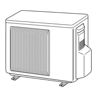
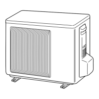
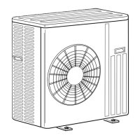
| Outdoor Unit Dimensions (W x H x D) | 800 x 550 x 285 mm |
| Indoor Unit Weight | 10 kg |
Detailed specifications for main electrical components used in the outdoor unit.
Specifies maximum refrigerant piping length and height difference limits.
Details the additional refrigerant charge required for longer piping lengths.
Charts showing cooling capacity and input based on indoor/outdoor temperatures.
Corrections for capacity and input based on compressor operating frequency.
Procedure for performing a test run operation of the air conditioner.
Performance data related to outdoor low pressure and unit current in different modes.
Explains the operation and control logic of the outdoor fan motor.
Details the control logic for the reversing valve (R.V.) coil in different modes.
Shows the relationship between sensors and actuators for unit control.
Instructions for changing the defrost finish temperature setting.
Configuration of the pre-heat control to prevent moisture interference.
Important safety precautions and checks before troubleshooting the unit.
Procedure to recall and identify past failure modes of the unit.
A table detailing symptoms, LED indications, conditions, and remedies for troubleshooting.
Criteria and methods for checking the normal operation of key components.
Step-by-step troubleshooting procedures for various unit issues.
Diagrams and voltage measurements for diagnosing electronic control boards.
Step-by-step guide to removing the external cabinet of the outdoor unit.
Procedure for removing the inverter and power boards.
Steps to remove the inverter assembly and P.C. board for the E3 model.
Instructions for removing the reversing valve (R.V.) coil.
Guide to removing various thermistors from the unit.
Procedure for removing the outdoor fan motor assembly.
Steps for removing the compressor and the 4-way valve.
Instructions for removing the reactor component.
List of structural, electrical, and functional parts for MUZ-GB50VA-E1/E2 models.
List of structural, electrical, and functional parts for MUZ-GB50VA-E3 model.
List of accessories provided with the outdoor unit.