HFC
utilized
R410A
INDOOR UNIT
SERVICE MANUAL
No. OBH733
REVISED EDITION-G
Indoor unit service manual
MSZ-GL•NA, MSY-GL•NA Series (OBH732)
MUZ-GL18/24NA
MUZ-GL18/24NAH
MUY-GL18/24NA
PARTS CATALOG (OBB733)
OBH733 REVISED EDITION-F is void.
Revision G:
• MUZ-GL09/12/15NA(H)-
U2
and
MUY-GL09/12/15NA-
U2
have been added.
CONTENTS
1. TECHNICAL CHANGES ··································· 2
2. PART NAMES AND FUNCTIONS ····················· 3
3. SPECIFICATION ················································ 4
4. OUTLINES AND DIMENSIONS ························ 7
5. WIRING DIAGRAM ············································ 9
6. REFRIGERANT SYSTEM DIAGRAM ············· 21
7. DATA ································································ 24
8. ACTUATOR CONTROL ··································· 39
9. SERVICE FUNCTIONS ··································· 40
10. TROUBLESHOOTING ····································· 41
11. DISASSEMBLY INSTRUCTIONS ···················· 65
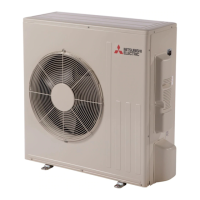
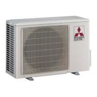
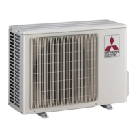
OUTDOOR UNIT
Models
MUZ-GL09NA
-
U1
,
U2
,
U8
MUZ-GL09NAH
-
U1
,
U2
,
U8
MUY-GL09NA
-
U1
,
U2
MUZ-GL12NA
-
U1
,
U2
MUZ-GL12NAH
-
U1
,
U2
MUY-GL12NA
-
U1
,
U2
MUZ-GL15NA
-
U1
,
U2
MUZ-GL15NAH
-
U1
,
U2
MUY-GL15NA
-
U1
,
U2
MUZ-GL18NA
-
U1
MUZ-GL18NAH
-
U1
MUY-GL18NA
-
U1
MUZ-GL24NA
-
U1
,
U2
MUZ-GL24NAH
-
U1
MUY-GL24NA
-
U1