Do you have a question about the Mitsubishi Electric MUZ-GE09NA and is the answer not in the manual?
| Cooling Capacity | 9, 000 BTU/h |
|---|---|
| Heating Capacity | 10, 000 BTU/h |
| Energy Efficiency Ratio (EER) | 12.1 |
| HSPF | 10.0 |
| HSPF Rating | 10.0 |
| Refrigerant | R410A |
| Operating Temperature (Cooling) | 14°F to 115°F |
| Power Supply | 208/230V, 1Ph, 60Hz |
| Voltage | 230V |
Details model additions and component updates across different revisions of the manual.
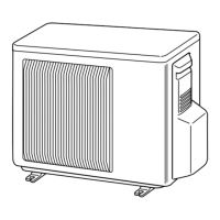
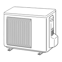
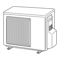
Identifies external components of the outdoor unit with diagrams and labels.
Detailed specifications including capacity, power, EER, dimensions, and refrigerant charge.
Covers power supply details and operating conditions for cooling and heating modes.
Provides detailed physical dimensions and required clearances for MUZ-GE09/12/15NA models.
Shows physical dimensions and installation clearances for MUZ-GE18NA models.
Displays physical dimensions and installation clearances for MUZ-GE24NA models.
Illustrates the electrical wiring for MUZ-GE09/12NA outdoor units, including inverter board.
Provides electrical wiring diagrams for MUZ-GE15NA outdoor units and related components.
Shows the electrical wiring diagrams for MUZ-GE18NA outdoor units and their components.
Displays the electrical wiring diagrams for MUZ-GE24NA outdoor units and associated circuitry.
Diagrams illustrating the refrigerant circuit and flow for MUZ-GE09/12/15NA models.
Shows the refrigerant circuit and flow diagrams for MUZ-GE18/24NA outdoor units.
Tables detailing cooling capacity at various conditions and correction factors for piping length.
Data showing heating capacity (TC, TPC) across different temperature ranges.
Graphs illustrating cooling capacity and power consumption based on operating temperatures.
Charts depicting heating capacity and power consumption versus operating temperatures.
Graphs showing condensing and suction pressures for cooling and heating modes.
A summary table of key operating parameters under standard conditions for various models.
Explains the control logic for the outdoor fan motor and the reversing valve (R.V. coil).
Details how sensors influence the operation of actuators like compressor, LEV, and fans.
Instructions for modifying the defrost finish temperature using jumpers on the P.C. board.
Describes the pre-heat control function and how to enable/disable it for low-temperature operation.
Safety guidelines and initial steps for diagnosing issues with the air conditioner.
Guide to recalling and understanding error codes indicated by the unit's LEDs for diagnosis.
A table listing specific outdoor unit faults, their LED indications, conditions, and remedies.
A comprehensive check table correlating symptoms with LED codes and detailed criteria for testing main parts.
Diagnostic flowcharts for troubleshooting the inverter, compressor, power supply, and other critical components.
Steps to verify the function and resistance characteristics of the electronic expansion valve (LEV).
Procedures for diagnosing issues with the inverter P.C. board, including fuse checks and LED status.
Guidance on identifying and resolving problems related to wiring errors and communication failures.
Steps to identify and mitigate electromagnetic interference affecting TV sets or radios.
Step-by-step instructions for disassembling the outdoor unit cabinet and internal parts.
Procedures for safely disassembling the outdoor unit cabinet and its internal components.
Detailed steps for disassembling the outdoor unit cabinet and accessing internal parts.