Do you have a question about the Mitsubishi Electric MUZ-GE35VA2-a2 and is the answer not in the manual?
| Cooling Capacity | 3.5 kW |
|---|---|
| Heating Capacity | 4.0 kW |
| Power Supply | 220-240 V, 50 Hz |
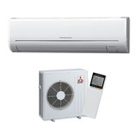
| Type | Split System |
| Indoor Unit Noise Level | 28-45 dB(A) |
| Outdoor Unit Noise Level | 50 dB(A) |
| Noise Level (Indoor Unit) | 28-45 dB(A) |
| Noise Level (Outdoor Unit) | 50 dB(A) |
Electrical wiring schematic for specific outdoor unit models.
Electrical wiring schematic for specific outdoor unit models.
Electrical wiring schematic for specific outdoor unit models.
Electrical wiring schematic for specific outdoor unit models.
Electrical wiring schematic for specific outdoor unit models.
Electrical wiring schematic for specific outdoor unit models.
Electrical wiring schematic for specific outdoor unit models.
Electrical wiring schematic for specific outdoor unit models.
Electrical wiring schematic for specific outdoor unit models.
Electrical wiring schematic for specific outdoor unit models.
Safety precautions and general checks before troubleshooting.
Flowchart for recalling failure modes on indoor/outdoor units.
Table listing abnormal points, LED indications, conditions, and remedies.
Table mapping symptoms, LED indications, and conditions to remedies.
Criteria for checking thermistor resistance with a tester.
Criteria for checking compressor and fan motor resistance.
Criteria for checking R.V. coil and LEV coil resistance.
Step-by-step guide for inverter and compressor checks.
Procedure to check for open phase in the compressor circuit.
Procedure to check the compressor's normal operation.
Procedure to measure compressor operation time until overcurrent.
Procedure to check for compressor start failure.
Procedure to check the R.V. coil for defects.
Diagram showing test points and voltage readings on the inverter P.C. board.
Procedure for removing the compressor and 4-way valve.