EasyManua.ls Logo

Mitsubishi Electric MUZ-GE50VA-a1 User Manual

Mitsubishi Electric MUZ-GE50VA-a1
96 pages
To Next Page IconTo Next Page
Page #1 background imageLoading...
Page #1 background image
SERVICE MANUAL
CONTENTS
1. TECHNICAL CHANGES ··································· 3
2. PART NAMES AND FUNCTIONS ····················· 4
3. SPECIFICATION ················································ 6
4. NOISE CRITERIA CURVES ·····························11
5. OUTLINES AND DIMENSIONS ······················ 13
6. WIRING DIAGRAM ·········································· 15
7. REFRIGERANT SYSTEM DIAGRAM ············· 27
8. PERFORMANCE CURVES ····························· 31
9. ACTUATOR CONTROL ··································· 63
10. SERVICE FUNCTIONS ···································· 64
11. TROUBLESHOOTING ····································· 65
12. DISASSEMBLY INSTRUCTIONS ···················· 86
SPLIT-TYPE AIR CONDITIONERS
NOTE:
RoHS compliant products have <G> mark on the spec name plate.
HFC
utilized
R410A
OUTDOOR UNIT
Indoor unit service manual
MSZ-GE•VA Series (OBH531)
PARTS CATALOG (OBB532)
MUZ-GE25VA
MUZ-GE25VAD
MUZ-GE33VA
MUZ-GE35VA
MUZ-GE35VA2
MUZ-GE35VAD
MUZ-GE42VA
MUZ-GE42VAD
Models
MUZ-GE25VA
-
A1
MUZ-GE50VA
-
A1
MUZ-GE25VA
-
A2
MUZ-GE50VA2
-
A1
MUZ-GE25VAD
-
A1
MUZ-GE50VAD
-
A1
MUZ-GE33VA
-
A1
MUZ-GE60VA
-
A1
MUZ-GE35VA
-
A1
MUZ-GE60VAD
-
A1
MUZ-GE35VA2
-
A1
MUZ-GE71VA
-
A1
MUZ-GE35VA2
-
A2
MUZ-GE71VAD
-
A1
MUZ-GE35VAD
-
A1
MUZ-GE80VA
-
A1
MUZ-GE42VA
-
A1
MUZ-GE80VA2
-
A1
MUZ-GE42VAD
-
A1
MUZ-GE80VAD
-
A1
No. OBH532
REVISED EDITION-E
Please void OBH532 REVISED EDITION-D.
Revision E:
MUZ-GE25VAD-
A1
, MUZ-GE35VAD-
A1
, MUZ-GE42VAD-
A1
,
MUZ-GE50VAD-
A1
, MUZ-GE60VAD-
A1
, MUZ-GE71VAD-
A1
and MUZ-GE80VAD-
A1
have been added.
Question and Answer IconNeed help?

Do you have a question about the Mitsubishi Electric MUZ-GE50VA-a1 and is the answer not in the manual?

Mitsubishi Electric MUZ-GE50VA-a1 Specifications

General IconGeneral
BrandMitsubishi Electric
ModelMUZ-GE50VA-a1
CategoryAir Conditioner
LanguageEnglish

Summary

Service Manual Introduction and Specifications

Models Covered and Revisions

Lists covered models and revision E information, including refrigerant usage guidelines.

1 Technical Changes

Details modifications and updates made to various outdoor unit models.

2 Part Names and Functions

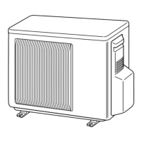
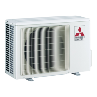
Identifies external components of the outdoor unit for different model series.

3 Specifications and Noise Criteria

Provides technical specifications and noise level data for outdoor units.

5 Outlines and Dimensions

Shows physical measurements and required installation space for outdoor units.

System Diagrams and Performance Data

6 Wiring Diagram

Illustrates electrical wiring schematics for various outdoor unit models.

7 Refrigerant System Diagram

Depicts the refrigerant circuit layout for different model series.

Refrigerant Piping and Charge Guidelines

Details maximum refrigerant piping length, height difference, and charge requirements.

8 Performance Data

Covers performance curves, compressor frequency correction, test runs, and operational data.

Control, Service, and Troubleshooting

9 Actuator Control Logic

Explains the interaction between main sensors and actuators like fans and coils.

10 Service Functions

Describes maintenance and diagnostic features like defrost and pre-heat control.

11 Troubleshooting Overview

Provides general fault-finding guidelines, cautions, and procedures.

Failure Mode Recall and Tables

Details diagnostic features for recalling past errors and failure mode tables.

Trouble Criteria and Flowcharts

Lists component fault diagnosis criteria and step-by-step troubleshooting flowcharts.

Test Point Diagrams and Noise Issues

Shows electrical test points and guidelines for troubleshooting electromagnetic noise.

Disassembly Instructions

General Terminal Detaching Points

Illustrates how to detach terminals with and without locking mechanisms.

Model-Specific Cabinet Removal

Provides steps for removing the cabinet for various model series.

Inverter Assembly and Component Removal

Details removing the inverter, R.V. coil, thermistors, fan motor, and compressor.

Related product manuals