Do you have a question about the Mitsubishi Electric MUZ-GE25VAD-a1 and is the answer not in the manual?
| Category | Air Conditioner |
|---|---|
| Brand | Mitsubishi Electric |
| Model | MUZ-GE25VAD-a1 |
| Cooling Capacity | 2.5 kW |
| Heating Capacity | 3.2 kW |
| Power Supply | 220-240 V, 50 Hz |
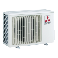
| Outdoor Unit Dimensions (H x W x D) | 550 x 800 x 285 mm |
| Weight (Indoor Unit) | 9 kg |
| Outdoor Unit Dimensions (WxHxD) | 800 x 550 x 285 mm |
| Indoor Unit Weight | 9 kg |
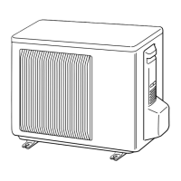
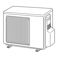
Dimensions and installation space for models.
Dimensions and installation space for models.
Dimensions and installation space for models.
Wiring diagrams for specific models.
Wiring diagrams for specific models.
Important precautions before troubleshooting.
Detailed flowchart for recalling failure modes.
Table listing failure modes, conditions, and remedies.
Table of symptoms, LED indications, and conditions.
Flowchart for checking inverter and compressor.
Procedure to check compressor start failure.
Check procedure for outdoor thermistors.
Check procedure for outdoor fan motor.
Flowchart for checking power supply.
Procedure to check LEV (Expansion Valve).
Steps to check the inverter P.C. board.
Procedures to check for miswiring and serial signal errors.
Test points and voltage diagrams for inverter P.C. board.