EasyManua.ls Logo

Mitsubishi Electric MUZ-GE50VA2-a1 User Manual

Mitsubishi Electric MUZ-GE50VA2-a1
96 pages
To Next Page IconTo Next Page
Page #1 background imageLoading...
Page #1 background image
SERVICE MANUAL
CONTENTS
1. TECHNICAL CHANGES ··································· 3
2. PART NAMES AND FUNCTIONS ····················· 4
3. SPECIFICATION ················································ 6
4. NOISE CRITERIA CURVES ·····························11
5. OUTLINES AND DIMENSIONS ······················ 13
6. WIRING DIAGRAM ·········································· 15
7. REFRIGERANT SYSTEM DIAGRAM ············· 27
8. PERFORMANCE CURVES ····························· 31
9. ACTUATOR CONTROL ··································· 63
10. SERVICE FUNCTIONS ···································· 64
11. TROUBLESHOOTING ····································· 65
12. DISASSEMBLY INSTRUCTIONS ···················· 86
SPLIT-TYPE AIR CONDITIONERS
NOTE:
RoHS compliant products have <G> mark on the spec name plate.
HFC
utilized
R410A
OUTDOOR UNIT
Indoor unit service manual
MSZ-GE•VA Series (OBH531)
PARTS CATALOG (OBB532)
MUZ-GE25VA
MUZ-GE25VAD
MUZ-GE33VA
MUZ-GE35VA
MUZ-GE35VA2
MUZ-GE35VAD
MUZ-GE42VA
MUZ-GE42VAD
Models
MUZ-GE25VA
-
A1
MUZ-GE50VA
-
A1
MUZ-GE25VA
-
A2
MUZ-GE50VA2
-
A1
MUZ-GE25VAD
-
A1
MUZ-GE50VAD
-
A1
MUZ-GE33VA
-
A1
MUZ-GE60VA
-
A1
MUZ-GE35VA
-
A1
MUZ-GE60VAD
-
A1
MUZ-GE35VA2
-
A1
MUZ-GE71VA
-
A1
MUZ-GE35VA2
-
A2
MUZ-GE71VAD
-
A1
MUZ-GE35VAD
-
A1
MUZ-GE80VA
-
A1
MUZ-GE42VA
-
A1
MUZ-GE80VA2
-
A1
MUZ-GE42VAD
-
A1
MUZ-GE80VAD
-
A1
No. OBH532
REVISED EDITION-E
Please void OBH532 REVISED EDITION-D.
Revision E:
MUZ-GE25VAD-
A1
, MUZ-GE35VAD-
A1
, MUZ-GE42VAD-
A1
,
MUZ-GE50VAD-
A1
, MUZ-GE60VAD-
A1
, MUZ-GE71VAD-
A1
and MUZ-GE80VAD-
A1
have been added.
Question and Answer IconNeed help?

Do you have a question about the Mitsubishi Electric MUZ-GE50VA2-a1 and is the answer not in the manual?

Mitsubishi Electric MUZ-GE50VA2-a1 Specifications

General IconGeneral
BrandMitsubishi Electric
ModelMUZ-GE50VA2-a1
CategoryAir Conditioner
LanguageEnglish

Summary

Outdoor Unit Service Manual

Refrigerant and Safety Information

Specified Refrigerant Usage

Emphasizes using only the correct refrigerant to prevent hazards and ensure proper operation.

Unit Specifications

Physical Dimensions and Installation Space

Outlines and Dimensions

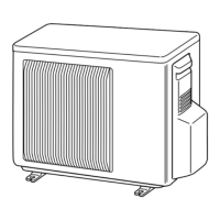
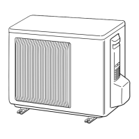
Shows external views, dimensions, and installation clearances for outdoor units.

Electrical Schematics

Wiring Diagrams

Illustrates the electrical connections for various outdoor unit models.

Refrigerant System Configuration

Refrigerant System Diagrams

Depicts the refrigerant flow and component layout for outdoor units.

Troubleshooting Procedures

Troubleshooting Safety Cautions

Provides essential safety precautions and checks before troubleshooting.

Failure Mode Recall Function

Recall Function Flowchart

Illustrates the step-by-step process for recalling failure modes.

Outdoor Unit Failure Mode Identification

Outdoor Unit Failure Mode Table

Lists abnormal points, LED indications, conditions, remedies, and recall functions.

Troubleshooting Check Table

Component Trouble Diagnosis

Trouble Criteria of Main Parts

Provides methods and criteria for checking the operability of major components.

Troubleshooting Flowcharts

Inverter and Compressor Diagnosis

Outlines the diagnostic steps for checking the inverter and compressor.

Power Supply Check Procedure

Guides through checking the power supply and bus-bar voltages.

Inverter P.C. Board Diagnosis

Outlines the procedure for checking the inverter P.C. board, including fuse and LED status.

Miswiring and Serial Signal Error Check

Details how to identify and resolve miswiring or serial signal communication errors.

Disassembly Instructions

Related product manuals