EasyManua.ls Logo

Mitsubishi Electric MUZ-DM25VA User Manual

Mitsubishi Electric MUZ-DM25VA
44 pages
To Next Page IconTo Next Page
Page #1 background imageLoading...
Page #1 background image
Models
MUZ-DM25VA
-
E1
,
ER1
,
ET1
MUZ-DM35VA
-
E1
,
ER1
,
ET1
OUTDOOR UNIT
SERVICE MANUAL
No. OBH751
CONTENTS
1. TECHNICAL CHANGES ······························2
2. PART NAMES AND FUNCTIONS ··················3
3. SPECIFICATION ········································4
4. NOISE CRITERIA CURVES ··························6
5. OUTLINES AND DIMENSIONS ·····················7
6. WIRING DIAGRAM ·····································8
7. REFRIGERANT SYSTEM DIAGRAM ·············9
8. PERFORMANCE CURVES ························ 10
9. ACTUATOR CONTROL ····························· 20
10. SERVICE FUNCTIONS ······························ 21
11. TROUBLESHOOTING ······························· 22
12. DISASSEMBLY INSTRUCTIONS ················· 40
HFC
utilized
R410A
Indoor unit service manual
MSZ-DM•VA Series (OBH750)
NOTE:
RoHS compliant products have <G> mark on the spec name plate.
PARTS CATALOG (OBB751)
Question and Answer IconNeed help?

Do you have a question about the Mitsubishi Electric MUZ-DM25VA and is the answer not in the manual?
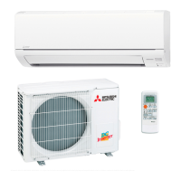
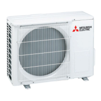
Mitsubishi Electric MUZ-DM25VA Specifications

General IconGeneral
TypeSplit System
Cooling Capacity2.5 kW
Heating Capacity3.2 kW
RefrigerantR32
Power Supply220-240 V, 50 Hz
Indoor Unit Weight9 kg
Operating Temperature Range (Cooling)-10°C to 46°C
Operating Temperature Range (Heating)-15°C to 24°C

Summary

Specifications

Wiring Diagram

Refrigerant System Diagram

Performance Curves

Actuator Control

Service Functions

Troubleshooting

Cautions on Troubleshooting

Important precautions and safety measures before and during troubleshooting.

Failure Mode Recall Function

Procedure to recall and analyze memorized abnormal conditions.

Troubleshooting Check Table

Table listing symptoms, LED indications, conditions, and remedies for faults.

Trouble Criterion of Main Parts

Methods and criteria for checking the condition of key components.

Troubleshooting Flow

Step-by-step flowcharts for diagnosing inverter and compressor issues.

Test Point Diagram and Voltage

Diagrams of the inverter P.C. board with test points and voltage measurements.

Disassembly Instructions

Related product manuals