EasyManua.ls Logo

Mitsubishi Electric MUZ-GA50VA User Manual

Mitsubishi Electric MUZ-GA50VA
56 pages
To Next Page IconTo Next Page
Page #1 background imageLoading...
Page #1 background image
SERVICE MANUAL
CONTENTS
1. TECHNICAL CHANGES ····································3
2. PART NAMES AND FUNCTIONS······················6
3. SPECIFICATION·················································6
4. NOISE CRITERIA CURVES·······························7
5. OUTLINES AND DIMENSIONS ·························8
6. WIRING DIAGRAM ············································9
7. REFRIGERANT SYSTEM DIAGRAM··············12
8. PERFORMANCE CURVES······························15
9. ACTUATOR CONTROL····································26
10. SERVICE FUNCTIONS·····································27
11. TROUBLESHOOTING······································27
12. DISASSEMBLY INSTRUCTIONS·····················46
13. PARTS LIST······················································50
14. RoHS PARTS LIST···········································54
Wireless type
Models
SPLIT-TYPE, HEAT PUMP AIR CONDITIONERS
MUZ-GA50VA -
MUZ-GA60VA -
MUZ-GA60VA -
MUZ-GA60VA -
MUZ-GA71VA -
MUZ-GA71VA -
E2
E1
E3
E2
E1
E1
HFC
utilized
R410A
NOTE:
• RoHS compliant products have <G> mark on the spec name plate.
For servicing of RoHS compliant products, refer to the RoHS Parts List.
• Contents of SERVICE FUNCTIONS(10) have been removed.
No. OB389
REVISED EDITION-F
Indoor unit service manual
MSZ-GAVA Series (OB388)
Please void OB389 REVISED EDITION-E.
OUTDOOR UNIT
Revision F:
• MUZ-GA60VA- has been added.
E3
OB389F--1qxp 07.9.3 5:06 PM Page 1
Question and Answer IconNeed help?

Do you have a question about the Mitsubishi Electric MUZ-GA50VA and is the answer not in the manual?

Mitsubishi Electric MUZ-GA50VA Specifications

General IconGeneral
BrandMitsubishi Electric
ModelMUZ-GA50VA
CategoryAir Conditioner
LanguageEnglish

Summary

Technical Changes

Information for R410A Refrigerant

Details and precautions for using R410A refrigerant, comparing it with R22.

Part Names and Functions

Outdoor Unit Components

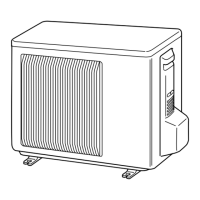
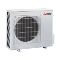
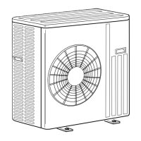
Illustrations and identification of the outdoor unit's external and internal components.

Specification

Electrical and Performance Data

Detailed electrical data, compressor, fan motor, and refrigerant specifications for different models.

Noise Criteria Curves

Sound Pressure Level by Frequency

Graphical representation of sound pressure levels at various band center frequencies under specified conditions.

Outlines and Dimensions

Unit Dimensions and Required Space

Diagrams showing the external dimensions and required installation clearance for the outdoor unit.

Wiring Diagram

Electrical Connections

Schematic showing the electrical connections between components and boards within the outdoor unit.

Refrigerant System Diagram

Refrigerant Flow and Components

Diagrams illustrating the refrigerant circuit, flow paths, and key components for different models.

Performance Curves

Capacity and Input Curves

Graphs showing cooling capacity and input based on indoor/outdoor conditions.

Capacity and Input Correction by Compressor Frequency

Correction factors for capacity and input based on compressor operational frequency.

Low Pressure and Unit Current Curves

Graphs illustrating outdoor low pressure and outdoor unit current under cooling operation.

Heat Operation Performance Data

Performance data tables for heat operation at various indoor and outdoor conditions.

Actuator Control

Outdoor Fan Motor Control

Timing and interlocking of the outdoor fan motor with the compressor operation.

R.V. Coil Control

Control logic for the reversing valve (R.V.) coil in heating, cooling, and dry modes.

Sensor and Actuator Relation

Table showing the relationship between various sensors and actuators in the system.

Troubleshooting

Cautions on Troubleshooting

Important safety and procedural precautions to be taken before and during troubleshooting.

Failure Mode Recall Function

Procedure for recalling and interpreting memorized failure codes for diagnosis.

Troubleshooting Flowchart

Step-by-step guide to diagnose and resolve common operational issues based on symptoms.

Troubleshooting Check Table

Table correlating LED indications and abnormal points with conditions and correspondences.

Trouble Criterion of Main Parts

Methods for checking the resistance and pressure of key components to determine faults.

Troubleshooting Flow

Flowchart for diagnosing issues when the outdoor unit does not operate, focusing on power supply checks.

Disassembly Instructions

Terminal Detaching Points

Methods for detaching terminals with and without locking mechanisms.

Cabinet Removal Procedure

Step-by-step guide to remove the outdoor unit's cabinet and panels.

Inverter and Board Removal

Procedure for removing the inverter assembly, P.C. boards, and power board.

Component Removal

Instructions for removing thermistors, fan motor, R.V. coil, compressor, and reactor.

Parts List (non-RoHS compliant)

Outdoor Unit Structural, Electrical, and Functional Parts

Illustrated list of structural, electrical, and functional parts for the outdoor unit.

Accessories

List of accessories provided with the outdoor unit.

RoHS Parts List (RoHS compliant)

RoHS Compliant Parts

Illustrated list of RoHS compliant structural, electrical, and functional parts for the outdoor unit.

RoHS Compliant Accessories

List of RoHS compliant accessories provided with the outdoor unit.

Related product manuals