Do you have a question about the Mitsubishi Electric MUZ-EF25VE and is the answer not in the manual?
| Category | Air Conditioner |
|---|---|
| Type | Split System |
| Cooling Capacity | 2.5 kW |
| Heating Capacity | 3.2 kW |
| Seasonal Energy Efficiency Ratio (SEER) | 8.5 |
| Power Supply | 220-240 V, 50 Hz |
| Refrigerant | R32 |
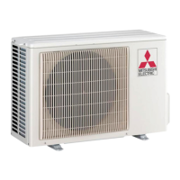
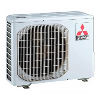
| Outdoor Unit Dimensions (HxWxD) | 550 x 800 x 285 mm |
| SEER | 8.5 |
| SCOP | 4.6 |
| Energy Efficiency Class (Cooling) | A+++ |
| Energy Efficiency Class (Heating) | A++ |
| Energy Efficiency Ratio (Heating) | 4.0 |
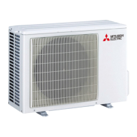
| Noise Level (Outdoor Unit) | 49 dB(A) |
| Outdoor Unit Dimensions (WxHxD) | 800 x 550 x 285 mm |
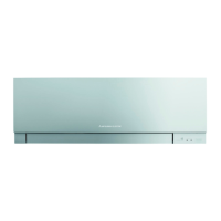
| Noise Level (Indoor Unit) | 19 dB |
Lists included accessories for the outdoor unit models.
Displays cooling capacity and input power based on indoor/outdoor conditions.
Shows how compressor frequency affects capacity and input.
Details the steps for performing a fixed-frequency test run operation.
Provides data on low pressure and current under various conditions.
Explains the ON/OFF control logic for the outdoor fan motor.
Details the control logic for the reversing valve (R.V.) coil.
Shows how sensors interact with actuators for system control.
Instructions on how to change the defrost finish temperature setting.
Explains the pre-heat control and its activation method.
Provides essential precautions before and during troubleshooting.
Explains how to recall and interpret failure modes for diagnosis.
Lists symptoms, LED indications, conditions, and remedies for troubleshooting.
Guides on checking the inverter and compressor for issues.
Procedure to check for open phase in the inverter output.
Steps to check compressor operation and condition.
Method for checking compressor winding resistance.
Procedure to measure compressor operation time before overcurrent.
Steps to diagnose compressor start-up failures.
Procedure for checking outdoor thermistor resistance and function.
Steps to check the R.V. coil for defects.
Procedure to check the outdoor fan motor's resistance and operation.
Steps to verify the power supply and its voltage levels.
Procedure to check the expansion valve (LEV) for proper function.
Steps to diagnose issues with the inverter P.C. board.
Provides test points and voltage readings for the inverter P.C. board.
Step-by-step guide for disassembling specific outdoor unit models.
Step-by-step guide for disassembling the MUZ-EF50VE outdoor unit.
Instructions for removing the inverter assembly and P.C. board.
Instructions for removing the R.V. coil.
Guide for removing various thermistors.
Instructions for removing the outdoor fan motor.
Steps to remove the compressor and 4-way valve.