Do you have a question about the Mitsubishi Electric MUZ-EF VG Series and is the answer not in the manual?
| Refrigerant | R32 |
|---|---|
| Power Supply | 220-240 V, 50 Hz |
| Wi-Fi Control | Optional (with additional adapter) |
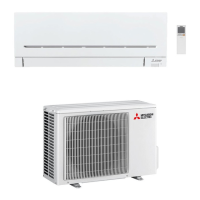
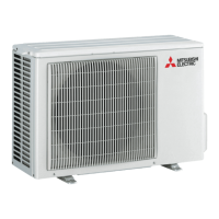
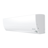
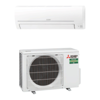
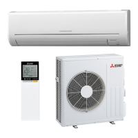
| Type | Air Conditioner |
| Series | MUZ-EF VG Series |
| Energy Efficiency Ratio (EER) | Varies by model |
| Features | Inverter Technology, Quiet Operation |
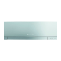
| Color | White |
| Energy Efficiency Class (Cooling) | A+++ |
| Airflow Direction | 4-way adjustable louvers |
Details new model additions for compatibility.
Notes a change in the indoor electronic control P.C. board.
Identifies and describes main parts of the indoor unit.
Lists and describes optional accessories for the unit.
Details electrical and performance specs for indoor units.
Specifies the model of the remote controller.
Lists specifications for key electric components.
Allows shortening of timer set times for service.
Assigns remote controllers to specific indoor units.
Enables automatic operation restart after power interruption.
Guides on connecting the Wi-Fi interface to MELCloud.
Details the functions and buttons of the wireless remote controller.
Explains the operation indicator lamps and their meanings.
Describes the procedures and features of Cool mode.
Describes the procedures and features of Dry mode.
Describes the procedures and features of Fan mode.
Describes the procedures and features of Heat mode.
Explains automatic switching between Cool and Heat modes.
Details automatic horizontal vane angle control and modes.
Instructions for setting ON/OFF timers.
Instructions for setting up weekly timer schedules.
Describes how to set and cancel the i-save function.
Guides on using emergency and test run modes.
Explains the compressor restart delay function.
Important safety warnings before performing troubleshooting.
Procedure to recall and diagnose past failure modes.
Step-by-step guide for diagnosing unit issues.
Table correlating indicator patterns to faults and remedies.
Specific checks and criteria for key components.
Diagnostic flow for indoor fan motor issues.
Procedure to check remote controller and indoor electronic board.
Detailed checks for the indoor PC board and fan motor.
Diagnostic flow tailored for specific VG/VGK models.
Diagnostic flow for 50VG/VGK models.
Procedure to diagnose miswiring and serial signal issues.
Troubleshooting serial signal and wiring for MXZ type.
Steps to address electromagnetic noise interference.
Step-by-step guide to remove the front panel.
Procedure to detach the indoor electrical box.
Instructions for removing the Wi-Fi interface unit.
Guide to removing various boards and components.
Instructions for removing the nozzle assembly.
Procedure to remove the horizontal vane motor.
Guide to removing the fan motor, thermistor, and fan.
Instructions for removing the Wi-Fi interface unit for VGKW models.