EasyManua.ls Logo

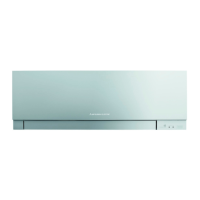
Mitsubishi Electric MUZ-AP VG Series User Manual

Mitsubishi Electric MUZ-AP VG Series
56 pages
To Next Page IconTo Next Page
Page #1 background imageLoading...
Page #1 background image
1
SERVICE MANUAL
INDOOR UNIT
PARTS CATALOG (OBB788)
No. OBH788
REVISED EDITION-C
Outdoor unit service manual
MUZ-AP∙VG/VGH Series (OBH789)
MXZ-D∙VA/VAH Series (OBH626)
MXZ-E∙VA/VAH Series (OBH723)
MXZ-F∙VF/VFH Series (OBH790)
CONTENTS
1. TECHNICAL CHANGES ∙∙∙∙∙∙∙∙∙∙∙∙∙∙∙∙∙∙∙∙∙∙∙∙∙∙∙∙∙∙∙∙∙∙∙ 3
2. PART NAMES AND FUNCTIONS ∙∙∙∙∙∙∙∙∙∙∙∙∙∙∙∙∙∙∙∙∙ 4
3. SPECIFICATION ∙∙∙∙∙∙∙∙∙∙∙∙∙∙∙∙∙∙∙∙∙∙∙∙∙∙∙∙∙∙∙∙∙∙∙∙∙∙∙∙∙∙∙∙∙∙∙∙ 6
4. NOISE CRITERIA CURVES ∙∙∙∙∙∙∙∙∙∙∙∙∙∙∙∙∙∙∙∙∙∙∙∙∙∙∙∙∙∙ 9
5. OUTLINES AND DIMENSIONS ∙∙∙∙∙∙∙∙∙∙∙∙∙∙∙∙∙∙∙∙∙∙∙11
6. WIRING DIAGRAM ∙∙∙∙∙∙∙∙∙∙∙∙∙∙∙∙∙∙∙∙∙∙∙∙∙∙∙∙∙∙∙∙∙∙∙∙∙∙∙∙∙∙ 12
7. REFRIGERANT SYSTEM DIAGRAM ∙∙∙∙∙∙∙∙∙∙∙∙∙ 18
8. SERVICE FUNCTIONS ∙∙∙∙∙∙∙∙∙∙∙∙∙∙∙∙∙∙∙∙∙∙∙∙∙∙∙∙∙∙∙∙∙∙∙ 19
9. MICROPROCESSOR CONTROL ∙∙∙∙∙∙∙∙∙∙∙∙∙∙∙∙∙∙∙ 21
10. TROUBLESHOOTING ∙∙∙∙∙∙∙∙∙∙∙∙∙∙∙∙∙∙∙∙∙∙∙∙∙∙∙∙∙∙∙∙∙∙∙∙∙ 29
11. DISASSEMBLY INSTRUCTIONS ∙∙∙∙∙∙∙∙∙∙∙∙∙∙∙∙∙∙∙∙ 45
OBH788 REVISED EDITION-B is void.
MSZ-AP25VG
MSZ-AP35VG
MSZ-AP42VG
MSZ-AP50VG
MSZ-AP25VGK
MSZ-AP35VGK
MSZ-AP42VGK
MSZ-AP50VGK
Revision C:
• MSZ-AP25/35/42VG-
E2
,
EN2
,
ET2
,
MSZ-AP25/35/42VGK-
E2
,
EN2
,
ET2
,
MSZ-AP50VG-
ER1
,
E2
,
EN2
,
ET2
,
MSZ-AP50VGK-
ER1
,
E2
,
EN2
,
ET2
,
MSZ-AP60/71VG-
ER1
,
E2
,
ET2
,
MSZ-AP60/71VGK-
ER1
,
E2
,
ET2
,
have been added.
Models
MSZ-AP25VG
-
E1
,
EN1
,
ET1
,
ER1
,
E2
,
EN2
,
ET2
MSZ-AP25VGK
-
E1
,
EN1
,
ET1
,
ER1
,
E2
,
EN2
,
ET2
MSZ-AP35VG
-
E1
,
EN1
,
ET1
,
ER1
,
E2
,
EN2
,
ET2
MSZ-AP35VGK
-
E1
,
EN1
,
ET1
,
ER1
,
E2
,
EN2
,
ET2
MSZ-AP42VG
-
E1
,
EN1
,
ET1
,
ER1
,
E2
,
EN2
,
ET2
MSZ-AP42VGK
-
E1
,
EN1
,
ET1
,
ER1
,
E2
,
EN2
,
ET2
MSZ-AP50VG
-
E1
,
EN1
,
ET1
,
ER1
,
E2
,
EN2
,
ET2
MSZ-AP50VGK
-
E1
,
EN1
,
ET1
,
ER1
,
E2
,
EN2
,
ET2
MSZ-AP60VG
-
E1
,
ET1
,
ER1
,
E2
,
ET2
MSZ-AP60VGK
-
E1
,
ET1
,
ER1
,
E2
,
ET2
MSZ-AP71VG
-
E1
,
ET1
,
ER1
,
E2
,
ET2
MSZ-AP71VGK
-
E1
,
ET1
,
ER1
,
E2
,
ET2
Question and Answer IconNeed help?

Do you have a question about the Mitsubishi Electric MUZ-AP VG Series and is the answer not in the manual?

Mitsubishi Electric MUZ-AP VG Series Specifications

General IconGeneral
BrandMitsubishi Electric
ModelMUZ-AP VG Series
CategoryAir Conditioner
LanguageEnglish

Summary

Technical Changes

Part Names and Functions

Accessories

Lists included accessories for the indoor units.

Specification

Noise Criteria Curves

Outlines and Dimensions

Wiring Diagram

Refrigerant System Diagram

Service Functions

8-1. Timer Short Mode

Shortens timer settings for service purposes.

8-2. How to Set Remote Controller Exclusively for a Particular Indoor Unit

Describes pairing remote controllers to specific indoor units.

8-3. Auto Restart Function

Explains the function that resumes operation from last settings after power interruption.

8-4. Wi-Fi Interface Setting Up (MSZ-AP-VGK)

Microprocessor Control

Indoor Unit Display Section

Explains the meaning of the operation indicator lamp states.

9-1. Cool () Operation

Details the COOL mode, including frost prevention and fan speed control.

9-2. Dry (0) Operation

9-3. Fan (8) Operation

9-4. Heat (0) Operation

9-5. Auto Change Over ・・・ Auto Mode Operation

9-6. Auto Vane Operation

9-7. Timer Operation

9-8. Weekly Timer Operation

9-9. Night Mode () Operation

9-10. i-save (3) Operation

9-11. Operation Lock

9-12. Emergency/Test Operation

9-13. 3-Minute Time Delay Operation

Troubleshooting

10-1. Cautions on Troubleshooting

Lists important precautions and checks before troubleshooting.

10-2. Failure Mode Recall Function

1. Flow Chart of Failure Mode Recall Function for the Indoor/Outdoor Unit

Provides a flowchart for recalling failure modes.

2. Table of Indoor Unit Failure Mode Recall Function

10-3. Instruction of Troubleshooting

1. Check of the Unit.

A flowchart guiding initial unit checks based on operation status.

2. Check of Wi-Fi Interface (MSZ-AP-VGK)

10-4. Troubleshooting Check Table

10-5. Trouble Criterion of Main Parts

10-6. Troubleshooting Flow

Check of Indoor Fan Motor

A flowchart for diagnosing indoor fan motor issues.

B Check of Remote Controller and Indoor Electronic Control P.C. Board

Check of Indoor P.C. Board and Indoor Fan Motor

How to Check Miswiring and Serial Signal Error

E Electromagnetic Noise Enters into TV Sets or Radios

10-7. Test Point Diagram and Voltage

Disassembly Instructions

2. Removing the Wi-Fi Interface (Photos 3, 5) MSZ-AP-VGK

How to Install the Wi-Fi Interface (Photo 3)

3. Removing the Indoor Electrical Box (Photos 3, 4, 5)

4. Removing the Indoor Terminal P.C. Board, the Switch Board, the Display Board, the Receiver Board and the Indoor Electronic Control P.C. Board

5. Removing the Nozzle Assembly

6. Removing the Vane Motors (U) (L) (Horizontal) and the Vane Motor (Vertical)

7. Removing the Line Flow Fan, the Indoor Fan Motor Assembly, the Indoor Coil Thermistor (Photo 9, 10, 11)

11-2. MSZ-AP60VG MSZ-AP71VG MSZ-AP60VGK MSZ-AP71VGK

1. Removing the Panel

Steps to remove the outer panels of the unit.

2. Removing the Wi-Fi Interface (Photos 3, 4) MSZ-AP-VGK

Guide to remove the Wi-Fi interface module.

How to Install the Wi-Fi Interface (Photo 3)

Instructions for installing the Wi-Fi interface module.
3. Removing the Indoor Terminal P.C. Board, the Indoor Electronic Control P.C. Board, the Display P.C. Board, Switch/Buzzer P.C. Board and the Receiver P.C. Board

4. Removing the Indoor Electrical Box

5. Removing the Nozzle Assembly

6. Removing the Vertical Vane Motor Unit

7. Removing the Horizontal Vane Motor

8. Removing the Water Cut, the Indoor Fan Motor, the Indoor Coil Thermistor, and the Line Flow Fan

Related product manuals