EasyManua.ls Logo

Mitsubishi Electric MUZ-A12YV-E1 User Manual

Mitsubishi Electric MUZ-A12YV-E1
40 pages
To Next Page IconTo Next Page
Page #1 background imageLoading...
Page #1 background image
SERVICE MANUAL
CONTENTS
1. TECHNICAL CHANGES ····································2
2. PART NAMES AND FUNCTIONS······················5
3. SPECIFICATION·················································5
4. NOISE CRITERIA CURVES·······························7
5. OUTLINES AND DIMENSIONS ·························8
6. WIRING DIAGRAM ············································9
7. REFRIGERANT SYSTEM DIAGRAM ··············11
8. PERFORMANCE CURVES······························12
9. ACTUATOR CONTROL····································21
10. SERVICE FUNCTIONS·····································22
11. TROUBLESHOOTING······································22
12. DISASSEMBLY INSTRUCTIONS·····················34
13. PARTS LIST······················································38
Wireless type
Models
No. OB328
REVISED EDITION-A
SPLIT-TYPE, HEAT PUMP AIR CONDITIONERS
MUZ-A09YV -
MUZ-A12YV -
MUZ-A09YVH -
MUZ-A12YVH -
E1
E1
E1
E1
MUZ-A09YV -
MUZ-A12YV -
MUZ-A09YVH -
MUZ-A12YVH -
E1
E1
E1
E1
Indication of
model name
NOTE:
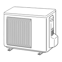
This service manual describes technical data of the outdoor units.
•As for indoor units MSZ-A09YV- and MSZ-A12YV- , refer to the service manual OB327.
•As for indoor unit MCFZ-A12WV- , refer to the service manual OB344.
E1
E1E1
HFC
utilized
R410A
Revision A:
MUZ-A12YV- and MUZ-A12YVH-
can be connected to MCFZ-A12WV- .
Some mistakes were corrected.
E1
E1E1
Please void OB328.
OB328 A--1qxp 04.4.26 4:49 PM Page 1
Mitsubishi Electric ilmalämpöpumput korjaa ja huoltaa pääkaupunkiseudulla: Jäähdytinpalvelu RefGroup Oy
www.ilmalämpöpumput.com

Questions and Answers:

Mitsubishi Electric MUZ-A12YV-E1 Specifications

General IconGeneral
Cooling Capacity3.5 kW
Heating Capacity4.0 kW
Power Supply220-240 V, 50 Hz
RefrigerantR32
Noise Level (Indoor Unit)19 dB

Summary

Technical Changes

Information for R410A Refrigerant

Details about R410A refrigerant, its properties, and installation considerations.

Tools for R410A Refrigerant Systems

Lists specialized tools required for R410A refrigerant systems.

Refrigerant Piping Specifications

Specifications for refrigerant pipes used with R410A systems.

Refrigerant Oil Application

Guidance on applying special refrigeration oil to flare and union surfaces.

Air Purge Procedures

Procedures and precautions for air purging in refrigerant circuits for environmental protection.

Additional Refrigerant Charging

Instructions for adding refrigerant, emphasizing liquid phase charging to prevent composition change.

Part Names and Functions

Specification

Noise Criteria Curves

Outlines and Dimensions

Wiring Diagram

Refrigerant System Diagram

Performance Curves

Guaranteed Voltage Range

Specifies the acceptable voltage range for operation.

Air Flow Settings

Instructions regarding air flow settings for optimal performance.

Main Readings for Performance

Lists key parameters to measure for performance evaluation.

Outdoor Low Pressure and Current Data

Presents data on low pressure and current under various operating conditions.

Cool Operation Performance Data

Performance data for cooling operation under different temperatures and humidity.

Heat Operation Performance Data

Performance data for heating operation under different temperatures.

Actuator Control

Outdoor Fan Motor Control

Explains the operation and interlocking of the outdoor fan motor with the compressor.

R.V. Coil Control Logic

Details the control logic for the R.V. coil in cooling and heating modes.

Sensor to Actuator Mapping

Maps sensors to their corresponding actuators and operational purposes.

Service Functions

Defrost Setting Adjustment

Instructions for changing the defrost finish temperature setting via jumper wires.

Troubleshooting

Troubleshooting Precautions

Important safety and procedural guidelines to follow before and during troubleshooting.

Troubleshooting Flowchart and Steps

Provides a flowchart and troubleshooting steps for various operational issues.

Troubleshooting Check Table

A table correlating LED indications and symptoms with specific causes and checkpoints.

Main Parts Trouble Criteria

Lists main components and their resistance/voltage criteria for checking defects.

Inverter and Compressor Checking Method

Detailed procedure for diagnosing inverter and compressor issues.

Open Phase Check

Method to check for open phases in the inverter output voltage.

Power Transistor Module Check

Procedure to test the resistance of the power transistor module for defects.

Compressor Checking Procedure

Steps to check compressor winding and operation time for abnormalities.

Outdoor Thermistor Checks

Steps to check the resistance of various outdoor thermistors.

R.V. Coil Check Procedure

Procedure to check the R.V. coil for defects and its effect on operation modes.

Outdoor Fan Motor Diagnosis

Steps to diagnose issues with the outdoor fan motor.

Power Supply Check

Procedure to check the incoming power supply and its distribution.

Current-Limiting Resistor Check

Method to check the current-limiting resistor for faults.

Expansion Valve (LEV) Check

Procedure to check the expansion valve for proper operation and resistance.

Defrost Heater Check

Steps to check the defrost heater and its associated components.

Mis-wiring and Serial Signal Error Diagnosis

Guide to diagnose and resolve mis-wiring and serial signal errors affecting outdoor unit operation.

Disassembly Instructions

Cabinet Removal Procedure

Step-by-step guide to remove the outdoor unit's cabinet.

Inverter and Power Board Removal

Instructions for removing the inverter and power circuit boards.

R.V. Coil Removal

Steps for removing the R.V. coil component.

Thermistor Removal (Defrost & Discharge)

Guide to remove the defrost and discharge temperature thermistors.

Outdoor Fan Motor Removal

Instructions for removing the outdoor fan motor.

Compressor and 4-Way Valve Removal

Steps to remove the compressor and the 4-way valve.

Parts List

Outdoor Unit Structural and Functional Parts

Lists structural and functional parts of the outdoor unit with part numbers.

Outdoor Unit Electrical Parts

Lists electrical components of the outdoor unit with their part numbers.

Drain Socket Part Information

Information and part number for the drain socket.

Related product manuals