Do you have a question about the Mitsubishi Electric MUZ-A18YV and is the answer not in the manual?
| Brand | Mitsubishi Electric |
|---|---|
| Model | MUZ-A18YV |
| Category | Air Conditioner |
| Language | English |
Details on using R410A refrigerant, emphasizing installation and handling points.
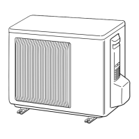
Diagram illustrating the external components and connection points of the outdoor unit.
Lists and identifies the standard accessories included with the outdoor unit.
Specifies the necessary clearance around the outdoor unit for proper installation and airflow.
Illustrates the electrical connections and component layout for the outdoor unit models.
Continuation of the wiring diagram, showing specific model connections and component references.
Diagram of the refrigerant circuit for MUZ-A18YV and MUZ-A24YV outdoor units.
Diagram of the refrigerant circuit for the MUZ-A26YV outdoor unit.
Details the maximum allowable vertical distance between indoor and outdoor units.
Provides guidelines for the amount of refrigerant to add based on piping length.
Specifies the voltage range for guaranteed operation of the air conditioner.
Instruction to set the air flow to the maximum setting for performance curve readings.
Lists the key parameters measured for performance curve analysis.
Step-by-step guide for measuring temperature differences for performance data.
Presents charts showing outdoor unit pressure and current under specific cooling conditions.
Details specific conditions for cooling operation analysis for performance curves.
Tables providing detailed cooling performance data (capacity, input) across various conditions.
Tables providing detailed heating performance data (capacity, input) across various conditions.
Explains the fan motor's operation linked to the compressor's on/off status.
Describes the control logic for the R.V. coil during heating and cooling modes.
Table mapping sensors to actuators (Compressor, LEV, Fan, 4-way valve) for system control.
Important safety precautions and checks to perform before starting troubleshooting.
Outlines the general steps for diagnosing and resolving operational issues.
Provides a flowchart for diagnosing unit malfunctions based on operating status.
A table correlating LED indicators and error modes with possible causes and check points.
Describes conditions where the outdoor unit operates but with reduced capacity, and checks to perform.
Details symptoms where the outdoor unit operates but specific issues arise, with corresponding checks.
Lists main components and their normal/abnormal resistance or pressure criteria for testing.
A flowchart for troubleshooting power supply issues when the outdoor unit does not operate.
Procedure for diagnosing and correcting mis-wiring or serial signal communication errors.
Troubleshooting steps for issues related to the R.V. coil in heating or cooling modes.
Troubleshooting steps for the Linear Expansion Valve (LEV) when it's suspected to be faulty.
Procedure for checking the inverter and compressor, including voltage and resistance measurements.
Guide for testing thermistors (discharge, defrost, heat exchanger, fin) for proper resistance.
Steps to diagnose issues with the outdoor fan motor, including resistance and voltage checks.
Troubleshooting procedure for the High Pressure Switch (HPS) when operation frequency is low.
Diagram and identification of the noise filter P.C. board and its connections.
Diagram and identification of the power board and its connectors and components.
Instructions on how to detach terminals with a locking mechanism for safe removal.
Step-by-step guide for safely removing the outer cabinet of the outdoor unit.
Detailed procedure for removing major internal electronic components.
Steps for removing the R.V. coil, a critical component in the refrigerant circuit.
Guide for removing various temperature sensors located on the outdoor unit.
Instructions for removing the outdoor fan motor and its components.
Procedure for safely removing the compressor and the 4-way valve.
Steps for locating and removing the reactor from the outdoor unit.
Lists structural and electrical parts of the outdoor unit with part numbers and quantities.
Lists the accessories included with the outdoor unit, such as drain socket and cap.