EasyManua.ls Logo

Mitsubishi Electric MUZ-SF25VE-E1 User Manual

Mitsubishi Electric MUZ-SF25VE-E1
52 pages
To Next Page IconTo Next Page
Page #1 background imageLoading...
Page #1 background image
SERVICE MANUAL
CONTENTS
1. TECHNICAL CHANGES ··································· 3
2. PART NAMES AND FUNCTIONS ····················· 4
3. SPECIFICATION ················································ 5
4. NOISE CRITERIA CURVES ······························ 6
5. OUTLINES AND DIMENSIONS ························ 8
6. WIRING DIAGRAM ············································ 9
7. REFRIGERANT SYSTEM DIAGRAM ··············11
8. PERFORMANCE CURVES ····························· 13
9. ACTUATOR CONTROL ··································· 27
10. SERVICE FUNCTIONS ···································· 28
11. TROUBLESHOOTING ····································· 28
12. DISASSEMBLY INSTRUCTIONS ···················· 45
Models
SPLIT-TYPE AIR CONDITIONERS
NOTE:
RoHS compliant products have <G> mark on the spec name plate.
HFC
utilized
R410A
No. OBH629
OUTDOOR UNIT
Indoor unit service manual
MSZ-SF•VE Series (OBH600)
PARTS CATALOG (OBB629)
MUZ-SF25VE MUZ-SF25VEH
MUZ-SF35VE MUZ-SF35VEH
MUZ-SF42VE MUZ-SF42VEH
MUZ-SF25VE
-
E1
MUZ-SF42VE
-
E1
MUZ-SF25VEH
-
E1
MUZ-SF42VEH
-
E1
MUZ-SF35VE
-
E1
MUZ-SF50VE
-
E1
MUZ-SF35VEH
-
E1
MUZ-SF50VEH
-
E1
Question and Answer IconNeed help?

Do you have a question about the Mitsubishi Electric MUZ-SF25VE-E1 and is the answer not in the manual?

Mitsubishi Electric MUZ-SF25VE-E1 Specifications

General IconGeneral
Cooling Capacity2.5 kW
Heating Capacity3.2 kW
Energy Efficiency Class (Cooling)A+++
Energy Efficiency Class (Heating)A++
Indoor Unit Noise Level19 dB(A)
RefrigerantR32
Dimensions (Outdoor Unit)550 x 800 x 285 mm
Power Supply220-240 V, 50 Hz
Outdoor Unit Dimensions (HxWxD)550 x 800 x 285 mm
TypeSplit System

Summary

CONTENTS

11. TROUBLESHOOTING

Guides on identifying and resolving operational issues and faults.

12. DISASSEMBLY INSTRUCTIONS

Step-by-step procedures for disassembling the outdoor unit.

3 SPECIFICATION

6 WIRING DIAGRAM

7 REFRIGERANT SYSTEM DIAGRAM

8 PERFORMANCE CURVES

10 SERVICE FUNCTIONS

11 TROUBLESHOOTING

11-1. CAUTIONS ON TROUBLESHOOTING

Safety precautions and preliminary checks before troubleshooting.

11-2. FAILURE MODE RECALL FUNCTION

How to recall and interpret error codes for diagnosing unit malfunctions.

Outdoor unit failure mode table

Table detailing outdoor unit error codes, conditions, and remedies.

11-3. TROUBLESHOOTING CHECK TABLE

A table listing symptoms, LED indications, abnormal points, and remedies.

11-4. TROUBLE CRITERION OF MAIN PARTS

Specifications and testing criteria for key internal components.

11-5. TROUBLESHOOTING FLOW

Comprehensive diagnostic procedures covering various components and issues.

11-5. TROUBLESHOOTING FLOW

Check of inverter/compressor

Diagnostic steps for checking the inverter and compressor.

Check of compressor winding

Procedure to measure compressor winding resistance.

Check of compressor operation time

Measuring the time until the compressor stops due to overcurrent.

Check of compressor start failure

Diagnosing issues preventing the compressor from starting.

Check of outdoor thermistors

Testing the resistance of outdoor thermistors.

Check of R.V. coil

Testing the resistance of the Reversing Valve (R.V.) coil.
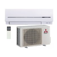
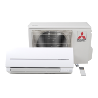
11-6. TEST POINT DIAGRAM AND VOLTAGE

12 DISASSEMBLY INSTRUCTIONS

Related product manuals