Do you have a question about the Mitsubishi Electric MUZ-HM09NA-U1 and is the answer not in the manual?
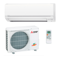
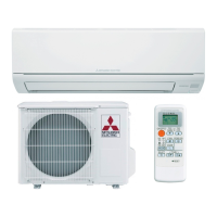
| Cooling Capacity | 9, 000 BTU |
|---|---|
| Heating Capacity | 10, 900 BTU |
| EER Rating | 12.5 |
| Refrigerant | R410A |
| Voltage | 208/230V |
| Compressor Type | Inverter |
| Weight (Indoor Unit) | 20 lbs |
| HSPF | 10.0 |
| Indoor Unit Weight | 20 lbs |
| Operating Temperature (Cooling) | 14°F to 115°F |
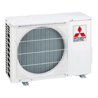
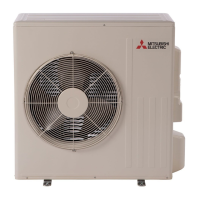
| Weight (Outdoor Unit) | 74 lbs |
| Power Supply | 208/230V, 60Hz |
| Type | Mini-Split Heat Pump |
Tables detailing cooling and heating capacities for various models.
Graphs showing cooling capacity and power consumption vs. temperature.
Safety precautions and general checks before starting troubleshooting.
Procedure to recall and interpret error codes from the unit.
Table listing symptoms, LED indications, conditions, and remedies.
Resistance/voltage checks for key components like thermistors and compressor.
Diagnostic steps for inverter and compressor issues.
Procedure to check for open phase in the inverter output.
Steps to check the compressor winding resistance.
How to measure compressor operation time before overcurrent.
Steps to diagnose and resolve compressor start failures.
Procedure to identify and resolve wiring and communication errors.
Diagrams showing test points and voltage readings on the inverter P.C. board.