Do you have a question about the Mitsubishi Electric MUZ-HJ25VA - E1 and is the answer not in the manual?
Lists electrical components and their specifications for each model, including capacitors, fuses, and modules.
Shows how compressor frequency affects cooling/heating capacity and input correction factors.
Detailed tables of cooling performance data at rated frequency for various conditions.
Detailed tables of heating performance data at rated frequency for various conditions.
Important safety precautions and preliminary checks before starting troubleshooting procedures.
A table correlating LED flash patterns with specific outdoor unit failures and remedies.
A comprehensive table listing symptoms, LED indications, conditions, and remedies for troubleshooting.
Methods and criteria for testing key electrical and mechanical components for proper function.
Step-by-step diagnostic flowcharts for identifying and resolving various operational issues.
| Cooling Capacity | 2.5 kW |
|---|---|
| Heating Capacity | 3.2 kW |
| Energy Efficiency Ratio (EER) | 3.21 |
| Coefficient of Performance (COP) | 3.61 |
| Power Supply | 220-240 V, 50 Hz |
| Refrigerant | R410A |
| Outdoor Unit Noise Level | 50 dB(A) |
| Indoor Unit Weight | 9 kg |
| Noise Level (Outdoor) | 50 dB(A) |
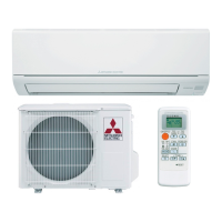
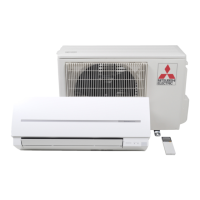
| Type | Air Conditioner |
| Indoor Unit Noise Level | 22-43 dB(A) |
| Dimensions (Outdoor Unit) | 550 x 800 x 285 mm |
| Noise Level (Indoor) | 19 dB (Low) |