Do you have a question about the Mitsubishi Electric MUZ-FD25VABH - E1 and is the answer not in the manual?
Details on updates and modifications to the product.
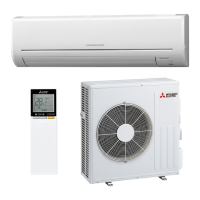
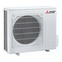
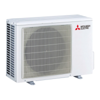
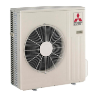
Identifies and explains the purpose of external components of the outdoor unit.
Comprehensive technical data and operating parameters for the outdoor units.
Lists the electrical components and their ratings used in the main models.
Presents noise level data across different frequency bands for cooling and heating.
Provides physical dimensions and required installation space for the outdoor units.
Illustrates the electrical connections and component layout for the outdoor units.
Shows the flow of refrigerant through the system components during operation.
Specifies limits for refrigerant pipe length and height difference, and additional charge calculation.
Graphical representation of cooling and heating capacity, and input power under various conditions.
Displays cooling capacity and input based on indoor/outdoor temperatures and humidity.
Shows how compressor frequency affects cooling/heating capacity and input power.
Instructions for performing a standard operational test run of the unit.
Presents data on outdoor low pressure and unit current in cooling and heating modes.
Detailed tables showing performance data for cooling and heating operations.
Explains the control logic for the outdoor fan motor, R.V. coil, and sensor-actuator relationships.
Details the ON/OFF interlocking logic of the outdoor fan motor with the compressor.
Describes the operation of the R.V. coil in different modes (Heating, Cooling, Dry).
Maps sensors to actuators for various operating conditions and protections.
Procedures for changing defrost settings and configuring pre-heat control.
How to adjust the defrost finish temperature for different models.
Instructions for activating the pre-heat control to prevent compressor start issues.
Important safety guidelines and checks before starting troubleshooting procedures.
How to recall and diagnose memorized fault conditions of the unit using indicator lamps.
Step-by-step guide to diagnose abnormalities using indicator lamps and beeps.
A detailed table listing symptoms, LED indications, abnormal points, conditions, and correspondences.
Methods and criteria for checking the resistance and condition of key electrical components.
Diagnostic flowcharts for specific components like the inverter and compressor.
Step-by-step process to diagnose inverter and compressor issues.
Diagrams illustrating test points on various circuit boards for voltage and resistance checks.
Identifies test points and connections on the inverter P.C. board.
Shows component layout and connector pin assignments for the outdoor control board.
Details the noise filter P.C. board layout and connections for MUZ-FD50VABH.
Illustrates the layout and connectors of the outdoor power board for MUZ-FD50VABH.
Shows the layout and connections for the relay P.C. board.
Step-by-step guide on how to safely disassemble the outdoor unit for maintenance.
Instructions for disassembling the cabinet of specific MUZ models.
Instructions for disassembling the cabinet of the MUZ-FD50VABH model.
| Brand | Mitsubishi Electric |
|---|---|
| Model | MUZ-FD25VABH - E1 |
| Category | Air Conditioner |
| Language | English |