Do you have a question about the Mitsubishi Electric MXZ-18TV and is the answer not in the manual?
Details changes from MXZ-18RV-E1 to MXZ-18TV-E1.
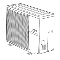
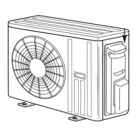
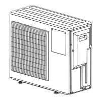
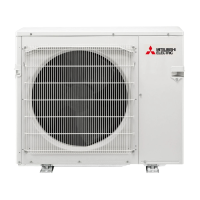
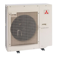
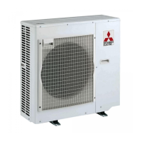
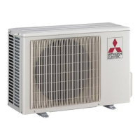
Identifies parts and functions of the outdoor unit.
Lists compatible indoor unit combinations with the outdoor unit.
Details cooling and heating capacities for various indoor unit combinations.
Lists specifications for the MXZ-18TV outdoor unit.
Details system specifications, capacities, and electrical data.
Provides specifications for compressor, fan motor, and other components.
Includes weight, sound level, refrigerant, oil, and test condition notes.
Presents noise levels across different frequencies for cooling and heating.
Provides detailed dimensions for the outdoor unit.
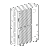
Specifies minimum clearances for proper ventilation and operation.
Illustrates the electrical connections and component layout for the outdoor unit.
Explains the various symbols used in the wiring diagram.
Depicts the refrigerant circuit, components, and flow paths for cooling and heating.
Details maximum allowable piping lengths and height differences.
Specifies pipe diameters for different indoor unit classes and connections.
Defines voltage range and air flow settings for performance evaluation.
Defines the temperature and input parameters used in performance analysis.
Provides a procedure for measuring specific indoor air temperature differences.
Graphs showing cooling and heating capacity/input vs. temperatures.
Performance curves for a single 07-class unit with varying frequency.
Performance curves for a single 09-class unit with varying frequency.
Performance curves for a single 12-class unit with varying frequency.
Graphs showing low pressure and current for 07-class unit in cooling and heating.
Instructions for operating the unit at a fixed frequency.
Instructions for operating the unit at a fixed frequency.
Instructions for operating the unit at a fixed frequency.
Overview of the control system for the multi-system inverter.
Details the functions of the outdoor unit's control microprocessor and its components.
Describes LEV opening based on indoor unit operating status.
Explains how standard LEV opening is determined based on frequency and capacity.
Details corrections for suction super heat and discharge temperature.
Procedure for correcting LEV opening based on suction super heat.
Correction method for LEV when multiple indoor units operate.
Lists operational frequency ranges for different capacity codes and modes.
Details conditions and procedures for heat defrosting.
Conditions for compressor start/stop and frequency adjustment based on discharge temperature.
Conditions and control details for refrigerant recovery during heating.
Explains fan speed control logic based on unit operation and frequency.
Maps sensors to their corresponding actuators for system control.
Important safety and preparation steps before and during troubleshooting.
Guide to troubleshooting the outdoor unit based on indicator status.
Table for diagnosing non-operation issues based on LED indicators.
Table for diagnosing intermittent operation issues.
Table for diagnosing issues when the unit operates with reduced performance.
Resistance checks for critical thermistors.
Resistance checks for compressor windings and fan motor.
Resistance checks for the reversing valve coil and linear expansion valve.
Troubleshooting steps to verify the power supply to the outdoor unit.
Troubleshooting steps for communication issues between units.
Troubleshooting procedure for R.V. coil during heating operation.
Troubleshooting procedure for R.V. coil during cooling operation.
Steps to check LEV operation and integrity.
Procedure to check output voltage to the compressor.
Procedure to check output balance to the compressor.
Procedure to check thermistor resistance and identify faulty units.
Procedure to check fan motor winding resistance and diagnose issues.
Explains behavior and troubleshooting when indoor units operate in different modes simultaneously.
Diagram showing test points and voltages on the main control board.
Graphs showing resistance vs. temperature for key thermistors.
Diagram of the noise filter P.C. board with component connections.
Steps for removing the top, back, and front panels.
Procedure for removing the inverter assembly and its main circuit board.
Procedure for removing the noise filter component.
Steps for removing the 4-way coil and temperature thermistors.
Procedure for removing the outdoor fan motor.
Steps to remove the compressor unit from the outdoor unit.
Lists functional components of the outdoor unit with part numbers.
Lists structural components of the outdoor unit with part numbers.
Details optional different-diameter piping kits for system expansion.
| Brand | Mitsubishi Electric |
|---|---|
| Model | MXZ-18TV |
| Category | Air Conditioner |
| Language | English |