EasyManua.ls Logo

Mitsubishi Electric MXZ-32NV User Manual

Mitsubishi Electric MXZ-32NV
62 pages
To Next Page IconTo Next Page
Page #1 background imageLoading...
Page #1 background image
SERVICE MANUAL
SPLIT-TYPE,HEAT PUMP AIR CONDITIONERS
CONTENTS
1. TECHNICAL CHANGES ····································2
2. PART NAMES AND FUNCTIONS······················2
3. INDOOR /OUTDOOR
CORRESPONDENCE TABLE··········3
4. INDOOR UNITS COMBINATION ·······················4
5. SPECIFICATION·················································9
6. OUTLINES AND DIMENSIONS························11
7. WIRING DIAGRAM ··········································13
8. REFRIGERANT SYSTEM DIAGRAM··············15
9. PERFORMANCE CURVES······························20
10. MICROPROCESSOR CONTROL ····················30
11. TROUBLESHOOTING······································39
12. DISASSEMBLY INSTRUCTIONS·····················53
13. PARTS LIST······················································57
14. OPTIONAL PARTS ····································BACK
Inverter-controlled multi system
Models
MXZ-18NV -
MXZ-32NV -
MXZ-18NV -
MXZ-32NV -
E2
E2
E1
E1
No. OB185
REVISED EDITION C
This manual describes technical data of outdoor unit.
For indoor unit refer to the service manuals No.OB207 and OB196 REVISED EDITION A of corresponding
models.
Model indication
Revision:
MXZ-18NV- and MXZ-18NV- have been added.
Page layout has been changed.
Performance curves has been modified.
The graph of the outdoor low pressure in the HEAT
operation of the PERFORMANCE CURVE of MXZ-
32NV was deleted.
Please void OB185 REVISED EDITION A and B.
E2E1
MXZ-32NV

Table of Contents

Question and Answer IconNeed help?

Do you have a question about the Mitsubishi Electric MXZ-32NV and is the answer not in the manual?

Mitsubishi Electric MXZ-32NV Specifications

General IconGeneral
Cooling Capacity3.2 kW
Heating Capacity3.6 kW
Power Supply220-240 V, 50 Hz
RefrigerantR410A
Indoor Unit Dimensions (WxHxD)Varies depending on the indoor unit model
Indoor Unit WeightVaries depending on the indoor unit model

Summary

1 TECHNICAL CHANGES

2 PART NAMES AND FUNCTION

Outdoor unit

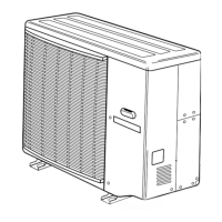
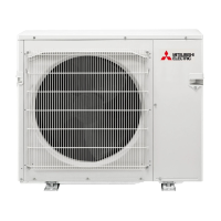
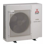
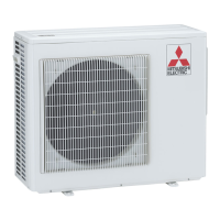
Details about the components and functions of the outdoor unit.

5 SPECIFICATION

6 OUTLINES AND DIMENSIONS

7 WIRING DIAGRAM

8 REFRIGERANT SYSTEM DIAGRAM

EVACUATION PROCEDURES

Step-by-step guide for evacuating the refrigerant system.

9 PERFORMANCE CURVES

Outdoor low pressure and outdoor unit current

Performance data related to outdoor pressure and current.

10 MICROPROCESSOR CONTROL

System organization

Overview of the microprocessor control system and its components.

LEV control

Standard LEV opening

Specifies standard LEV opening levels based on compressor operational frequency.

High and low pressure protection

High pressure protection in heating

Protection measures for high pressure conditions during heating.

11 TROUBLESHOOTING

Cautions on troubleshooting

Important safety precautions and preliminary checks before troubleshooting.

Simple check methods for inverter / compressor

Checking the compressor

Procedure to check the compressor's operation and winding.

Checking the outdoor thermistors

Checking the reversing valve coil

Procedure to check the integrity and operation of the reversing valve coil.

12 DISASSEMBLY PROCEDURE

Removing the compressor

Step-by-step guide for removing the compressor from the outdoor unit.

13 PARTS LIST

14 OPTIONAL PARTS

Different-diameter pipe

Details on different-diameter pipes for connecting indoor and outdoor units.

Related product manuals