EasyManua.ls Logo

Mitsubishi Electric PAC-MK54BC User Manual

Mitsubishi Electric PAC-MK54BC
28 pages
To Next Page IconTo Next Page
Page #1 background imageLoading...
Page #1 background image
May 2020
SPLIT-TYPE, HEAT PUMP AIR CONDITIONERS
TECHNICAL & SERVICE MANUAL
CONTENTS
1. SAFETY PRECAUTION ··································· 2
2. OVERVIEW OF UNIT ······································ 5
3. SPECIFICATIONS ·········································· 8
4. OUTLINES AND DIMENSIONS ························· 9
5. WIRING DIAGRAM ········································10
6
. NECESSARY CONDITIONS FOR SYSTEM CONSTRUCTION ············
11
7. TROUBLESHOOTING ····································15
8. DISASSEMBLY PROCEDURE ························· 24
BRANCH BOX
HFC
utilized
R410A
Note:
This service manual
describes technical data of
branch box. As for indoor
units and outdoor unit,
refer to its service manual.
PARTS CATALOG (OCB744)
PAC-MK54BC
No. OCH744
[Service Ref.]
PAC-MK54BC
PAC-MK34BC
[Model Name]
<Branch box>
PAC-MK54BC
PAC-MK34BC
Question and Answer IconNeed help?

Do you have a question about the Mitsubishi Electric PAC-MK54BC and is the answer not in the manual?

Mitsubishi Electric PAC-MK54BC Specifications

General IconGeneral
BrandMitsubishi Electric
ModelPAC-MK54BC
CategoryAir Conditioner
LanguageEnglish

Summary

SAFETY PRECAUTION

CAUTIONS RELATED TO NEW REFRIGERANT

Specific safety precautions for using R410A refrigerant and during repair service.

OVERVIEW OF UNIT

SYSTEM OUTLINE

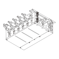
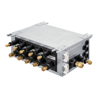
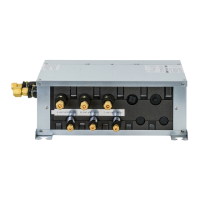
Describes the system configuration and function of the branch box with outdoor/indoor units.

INSTALLATION

Details space requirements and mounting considerations for branch box installation.

SPECIFICATIONS

OUTLINES AND DIMENSIONS

WIRING DIAGRAM

NECESSARY CONDITIONS FOR SYSTEM CONSTRUCTION

TRANSMISSION SYSTEM SETUP

Explains how to set up the M-NET transmission system and address settings for units.

REFRIGERANT SYSTEM DIAGRAM

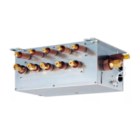
Illustrates the refrigerant flow and components within the branch box system.

TYPICAL CONTROL SYSTEM

Outlines common control system configurations and operational differences.

TROUBLESHOOTING

HOW TO CHECK THE PARTS

Procedures for checking thermistors and linear expansion valves for faults.

TEST POINT DIAGRAM

Visual guide to test points on the branch box controller board for diagnostics.

INTERNAL SWITCH FUNCTION TABLE

Details the function and settings of internal switches for various operations.

BRANCH BOX UNIT OPERATION MONITOR FUNCTION

Explains how to use the operation monitor function for diagnosis and status checks.

DISASSEMBLY PROCEDURE

Related product manuals