EasyManua.ls Logo

Mitsubishi Electric PEFY-P100VMM-E User Manual

Mitsubishi Electric PEFY-P100VMM-E
24 pages
To Next Page IconTo Next Page
Page #1 background imageLoading...
Page #1 background image
TECHNICAL & SERVICE MANUAL
Air-Conditioners For Building Application
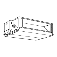
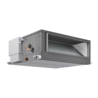
<Indoor unit>
PEFY-P20VMM-E,PEFY-P71VMM-E
PEFY-P25VMM-E,PEFY-P80VMM-E
PEFY-P32VMM-E,PEFY-P100VMM-E
PEFY-P40VMM-E,PEFY-P125VMM-E
PEFY-P50VMM-E,PEFY-P140VMM-E
PEFY-P63VMM-E
2004
Models
INDOOR UNIT
Ceiling Concealed
Series PEFY
CONTENTS
SAFETY PRECAUTIONS ·························1
1. FEATURES············································3
2. PART NAMES AND FUNCTIONS ········4
3. SPECIFICATION ···································6
4. OUTLINES AND DIMENSIONS············8
5. WIRING DIAGRAM ·····························10
6.
REFRIGERANT SYSTEM DIAGRAM
····12
7. TROUBLE SHOOTING························13
8. DISASSEMBLY PROCEDURE ···········18
For use with R410A & R407C & R22

Questions and Answers:

Mitsubishi Electric PEFY-P100VMM-E Specifications

General IconGeneral
BrandMitsubishi Electric
ModelPEFY-P100VMM-E
CategoryAir Conditioner
LanguageEnglish

Summary

Safety Precautions

Before Installation and Electric Work

Key safety instructions and requirements for unit installation and electrical work.

Precautions for R410A or R407C Refrigerant

Specific safety guidelines for handling refrigerants R410A and R407C.

Part Names and Functions

Wiring Diagram

Wiring for PEFY-P20 to P80 VMM-E

Schematic diagram illustrating the electrical connections for PEFY-P20 to PEFY-P80 VMM-E models.

Wiring for PEFY-P100 to P140 VMM-E

Schematic diagram illustrating the electrical connections for PEFY-P100 to PEFY-P140 VMM-E models.

Refrigerant System Diagram

Trouble Shooting

Component Testing Procedures

Guidelines for testing thermistors, motors, and expansion valves using resistance measurements.

Linear Expansion Valve Troubleshooting

Diagnosing issues with the linear expansion valve, including operation, noise, and connection problems.

Disassembly Procedure

Control Box Disassembly

Step-by-step instructions for removing and refitting the control box cover and components.

Related product manuals