SERVICE MANUAL
SPLIT-TYPE, HEAT PUMP AIR CONDITIONERS
SPLIT-TYPE, AIR CONDITIONERS
NOTE:
• This manual describes
only service data of the
indoor units.
• RoHS compliant products
have <G> mark on the
spec name plate.
CONTENTS
1. REFERENCE MANUAL
...................................
2
2. SAFETY PRECAUTION
...................................
3
3. PART NAMES AND FUNCTIONS
...................
4
4. SPECIFICATIONS
............................................
6
5. NOISE CRITERION CURVES
..........................
7
6. OUTLINES AND DIMENSIONS
.......................
8
7. WIRING DIAGRAM
..........................................
9
8. REFRIGERANT SYSTEM DIAGRAM
............
10
9. TROUBLESHOOTING
....................................
11
10. SPECIAL FUNCTION
.....................................
26
11. DISASSEMBLY PROCEDURE
.......................
29
Indoor unit
[Model names] [Service Ref.]
PARTS CATALOG (OCB453)
No. OCH453
March 2009
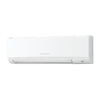
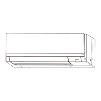
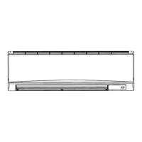
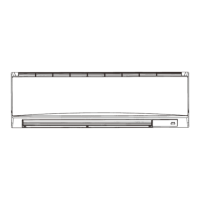
INDOOR UNIT
PKA-RP35HAL
PKA-RP35HAL
PKA-RP50HAL
PKA-RP50HAL