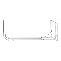
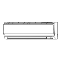
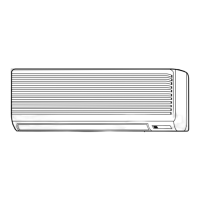
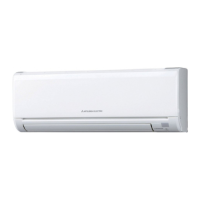
EasyManua.ls Logo

Mitsubishi Electric PKA-A12LA User Manual

Mitsubishi Electric PKA-A12LA
56 pages
To Next Page IconTo Next Page
Page #1 background imageLoading...
Page #1 background image
SERVICE MANUAL
Indoor unit
[Model Name] [Service Ref.]
PKA-A12LA
PKA-A12LA.TH
PKA-A18LA
PKA-A18LA.TH
PARTS CATALOG (OCB761)
INDOOR UNIT
SPLIT-TYPE, HEAT PUMP AIR CONDITIONERS
SPLIT-TYPE, AIR CONDITIONERS
No. OCH761
REVISED EDITION-A
May 2021
CONTENTS
1. REFERENCE MANUAL ······················2
2. SAFETY PRECAUTION ······················3
3. PARTS NAMES AND FUNCTIONS ·······5
4. SPECIFICATIONS ······························6
5. NOISE CRITERION CURVES ···············7
6. OUTLINES AND DIMENSIONS ············8
7. WIRING DIAGRAM ···························· 9
8. REFRIGERANT SYSTEM DIAGRAM··· 10
9. TROUBLESHOOTING ······················ 11
10. FUNCTION SETTING ······················· 26
11. SPECIAL FUNCTION ······················· 27
12. DISASSEMBLY PROCEDURE ··········· 29
13. REMOTE CONTROLLER ·················· 33
OCH761 is void.
Revision:
Outlines and dimensions
have been modified
in REVISED EDITION-A.

Questions and Answers:

Mitsubishi Electric PKA-A12LA Specifications

General IconGeneral
BrandMitsubishi Electric
ModelPKA-A12LA
CategoryAir Conditioner
LanguageEnglish

Summary

Reference Manual

Outdoor Unit Service Manual Details

Information regarding service manuals for outdoor units.

Safety Precautions

Always Observe for Safety

General safety rule before accessing terminals.

Cautions Related to New Refrigerant

Precautions for units using R410A refrigerant.

Preparation Before Repair Service

Steps and tools needed before starting repair work.

Refrigerant Piping Precautions

Guidelines for using and handling refrigerant pipes.

Refrigerant Oil and Handling Precautions

Proper oil types and contamination avoidance for refrigerant systems.

Refrigerant Handling and Storage

Safe practices for handling and storing refrigerants and components.

Specific Refrigerant Tools and Safety

Tools for R410A and general safety during service.

Warning for Service

General Service Warnings and Precautions

Important warnings and guidelines for performing service operations.

Cautions for Service Operations

Specific cautions to follow during service operations.

Additional Refrigerant Charge

Instructions for charging refrigerant directly from a cylinder.

Parts Names and Functions

Indoor Unit Components Identification

Labels and identification of parts on the indoor unit.

Service Tools for R410A Refrigerant

List and specifications of essential tools for R410A refrigerant service.

Specifications

PKA-A12LA.TH Indoor Unit Specifications

Technical specifications for the PKA-A12LA.TH indoor unit.

PKA-A18LA.TH Indoor Unit Specifications

Technical specifications for the PKA-A18LA.TH indoor unit.

Noise Criterion Curves

Noise Criterion Curves Analysis

Graphical representation of noise levels across different frequencies.

Outlines and Dimensions

Indoor Unit Dimensions and Installation Clearances

Detailed dimensions and required installation space for the indoor unit.

Wiring Diagram

Indoor Unit Wiring Diagram and Legend

Schematic representation of electrical connections and symbols.

Refrigerant System Diagram

Refrigerant Flow and Component Locations

Diagram illustrating refrigerant flow and key components in the system.

Troubleshooting

Troubleshooting Summary by Self-Diagnosis

Summary of troubleshooting steps based on self-diagnosis.

Malfunction Diagnosis by Remote Controller

Methods for diagnosing malfunctions using the remote controller.

Indoor Unit Error Codes

Table listing error codes and symptoms for indoor unit malfunctions.

Outdoor Unit Error Codes

Table listing error codes and symptoms for outdoor unit malfunctions.

Self-Diagnosis Action Table

Detailed troubleshooting steps for specific error codes.

Room Temperature Thermistor (TH1) Diagnosis

Diagnosis and countermeasures for room temperature sensor errors.

Pipe Temperature Thermistor (TH2) Diagnosis

Diagnosis and countermeasures for pipe temperature sensor errors.

Drain Float Switch and Overflow Protection

Troubleshooting drain float switch and overflow protection issues.

Freezing/Overheating Protection Diagnosis

Causes and solutions for freezing or overheating protection activation.

Pipe Temperature Detection Troubleshooting

Troubleshooting abnormal pipe temperature readings.

Condenser/Evaporator Thermistor (TH5) Diagnosis

Diagnosis for condenser/evaporator thermistor errors.

Abnormal Refrigerant Circuit Diagnosis

Actions for refrigerant circuit abnormalities and 4-way valve issues.

Remote Controller Transmission Error (E0/E4)

Troubleshooting remote controller signal transmission errors.

Remote Controller Transmission Error (E3/E5)

Diagnosing remote controller signal loss or transmission issues.

Indoor/Outdoor Unit Communication Error (E6)

Troubleshooting communication errors between units.

Indoor/Outdoor Unit Communication Error (E7)

Resolving signal reception errors between indoor and outdoor units.

Indoor Controller Board Errors (Fb)

Actions for indoor controller board data read errors.

Remote Controller Board Errors (E1/E2)

Troubleshooting remote controller board malfunctions.

Forced Compressor Stop (Water Leakage)

Procedures for compressor stops due to water leakage detection.

Fan Motor Troubleshooting (Pb)

Diagnosing and resolving indoor fan motor issues.

Troubleshooting of Problems: LED Status

Troubleshooting based on LED indicators on the indoor controller board.

Vane Performance and Wireless Receiver Issues

Troubleshooting vane operation and wireless receiver problems.

Emergency Operation Procedures

How to activate and use emergency operation modes.

How to Check the Parts

Procedures for checking thermistor and vane motor resistance values.

DC Fan Motor Troubleshooting Guide

Step-by-step guide to diagnose DC fan motor issues.

Indoor Controller Board Test Point Diagram

Diagram showing test points on the indoor controller board.

DIP Switch and Jumper Wire Settings

Configuration settings using DIP switches and jumper wires.

Function Setting

Unit Function Settings via Remote Controller

Setting unit functions like filter sign and fan speed using the remote.

Special Function

Rotation and Back-up Function Operation

Alternating operation of main and sub units for rotation and backup.

2nd Stage Cut-in Function Operation

How the second unit activates for higher cooling demand.

Setting Rotation and Back-up Functions

How to configure rotation and back-up functions via remote controller.

Setting 2nd Unit Cut-in Function

Configuring the 2nd stage cut-in function with request codes.

Disassembly Procedure

Removing the Front Panel and Corner Box

Step-by-step guide to remove the front panel and corner box.

Removing the Electrical Box

Procedure for safely removing the electrical box.

Removing Controller Boards and LED Boards

Steps to remove internal circuit boards.

Removing Nozzle Assembly and Drain Hose

Procedure for removing the nozzle assembly and drain hose.

Removing the Vane Motor

Guide to detach and remove the vane motor.

Removing Indoor Fan Motor and Line Flow Fan

Steps to remove the fan motor and line flow fan.

Removing Pipe and Condenser/Evaporator Thermistors

How to remove pipe and condenser/evaporator thermistors.

Removing the Heat Exchanger

Procedure for removing the heat exchanger assembly.

Removing the Room Temperature Thermistor (TH1)

Steps to disconnect and remove the room temperature thermistor.

Remote Controller

Remote Controller Functions Overview

Explanation of basic remote controller buttons and their functions.

Remote Controller Display Modes and Icons

Explanation of Full and Basic display modes and icons.

Main Menu Structure Navigation

Navigation flow for the remote controller's menu system.

Service Menu Options Overview

Overview of options available within the service menu.

Operation Menu Settings and Functions

Detailed settings for operation, timer, and energy saving modes.

Initial Setting Menu Options

Settings for basic configuration, clock, and administrator password.

Display Settings and Operation Modes

Configuration of display, auto mode, and setback mode.

Maintenance and Service Menu Details

Functions for error checking, test runs, and maintenance information.

PAR-FL32MA Controller Interface and Operation

Explanation of buttons and display for PAR-FL32MA remote.

PAR-SL100A-E Controller Interface and Display

Overview of buttons and display elements for PAR-SL100A-E remote.

13-2. Error Information

How to display and clear error information on the remote controller.

Checking Error Information via Maintenance Menu

Accessing error information through the maintenance menu.

13-3. Service Menu

Steps to enter the service menu using a password.

13-4. Test Run

Performing cooling, heating, and vane checks with PAR-40MAA.

PAR-FL32MA Test Run Procedure

Steps for performing test runs on PAR-FL32MA.

PAR-SL100A-E Test Run Procedure

How to initiate test runs using the PAR-SL100A-E remote.

13-5. Function Setting

Setting various functions for indoor units using PAR-40MAA.

PAR-FL32MA Function Selection Procedure

Selecting functions using the wireless remote controller for PAR-FL32MA.

PAR-SL100A-E Function Selection Procedure

Step-by-step guide for function selection on PAR-SL100A-E.

13-6. Error History

How to access and clear past error records.

13-7. Self-Diagnosis

Performing self-diagnosis and resetting errors with PAR-40MAA.

PAR-FL32MA Malfunction Diagnosis

Methods for diagnosing malfunctions on PAR-FL32MA.

PAR-SL100A-E Self-Check Procedure

Steps for performing self-checks on PAR-SL100A-E.

13-8. Remote Controller Check

Procedure to check the remote controller's functionality.

13-9. Smooth Maintenance

Steps to set up and run smooth maintenance operations.

13-10. Request Code

How to retrieve operation data and error history using request codes.

Related product manuals