R
Rebecca DanielsAug 11, 2025
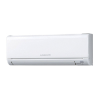
What to do if trouble is reoccurring in Mitsubishi Electric PKA-A12GA Air Conditioner?
- GGary RojasAug 11, 2025
Judge what is wrong and take a corrective action according to “SELF-DIAGNOSIS ACTION TABLE” (10-3).
What to do if trouble is reoccurring in Mitsubishi Electric PKA-A12GA Air Conditioner?
Judge what is wrong and take a corrective action according to “SELF-DIAGNOSIS ACTION TABLE” (10-3).
What to do if trouble is not reoccurring and is not logged in Mitsubishi Electric Air Conditioner?
Recheck the abnormal symptom. Identify the cause of the trouble and take a corrective action according to “TROUBLESHOOTING OF PROBLEMS” (10-4). Continue to operate the unit for the time being if the cause is not ascertained. This indicates there is no abnormality in electrical components, controller boards, remote controller, etc.
What to do if trouble is not reoccurring and is logged in Mitsubishi Electric PKA-A12GA Air Conditioner?
Consider temporary defects such as the operation of protection devices in the refrigerant circuit including the compressor, poor wiring connections, or noise. Re-check the symptom, and check the installation environment, refrigerant amount, weather conditions when the trouble occurred, and related wiring. Reset the error code logs and restart the unit after finishing the service. This indicates there is no abnormality in electrical components, controller boards, and the remote controller.
| Refrigerant | R410A |
|---|---|
| Type | Mini-Split |
| Cooling Capacity | 3.5 kW |
| Heating Capacity | 4.0 kW |
| Energy Efficiency Ratio (EER) | 11.0 |
| Seasonal Energy Efficiency Ratio (SEER) | 16.0 |
| Voltage | 220-240 V |
| Energy Efficiency Ratio (Cooling) | 3.5 |
| Energy Efficiency Ratio (Heating) | 4.0 |
| Indoor Unit Dimensions (HxWxD) | 295 x 800 x 223 mm |
| Outdoor Unit Dimensions (HxWxD) | 550 x 780 x 285 mm |
| Weight (Indoor Unit) | 9 kg |
| Weight (Outdoor Unit) | 32 kg |
| Indoor Unit Noise Level | 19 dB |
| Outdoor Unit Noise Level | 49 dB |
| Indoor Unit Dimensions (WxHxD) | 800 x 295 x 223 mm |
| Outdoor Unit Dimensions (WxHxD) | 780 x 550 x 285 mm |
| Indoor Unit Weight | 9 kg |
| Outdoor Unit Weight | 32 kg |
General safety guidelines to follow before accessing electrical terminals.
Specific precautions for handling R410A refrigerant and related tools.
Summary of error code display and actions for reoccurring or non-reoccurring troubles.
Procedure for diagnosing malfunctions using the remote controller.
Diagnoses and counter-measures for room temp, pipe temp, drain sensor, and drain pump errors.
Diagnoses and counter-measures for freezing/overheating and pipe temperature errors.
Diagnoses and counter-measures for pipe temp sensor, remote controller signal errors.
Diagnoses and counter-measures for communication, controller board, and compressor errors.
Troubleshooting steps when LED2 on the indoor controller board is off.
Troubleshooting for LED2 blinking, vane issues, and wireless receiver problems.
How to use emergency operation when the wireless remote is faulty.
How to use emergency operation when the wired remote or microprocessor fails.
Instructions for removing the front panel of the indoor unit.
Instructions for removing the lower side of the indoor unit from installation plate.
Instructions for removing the power board.
Instructions for removing the vane motor.
Instructions for removing the indoor controller board.
Instructions for removing room, pipe, and coil temperature thermistors.
Instructions for removing the nozzle assembly.