EasyManua.ls Logo

Mitsubishi Electric PKA-A18HA User Manual

Mitsubishi Electric PKA-A18HA
36 pages
To Next Page IconTo Next Page
Page #1 background imageLoading...
Page #1 background image
SERVICE MANUAL
SPLIT-TYPE, HEAT PUMP AIR CONDITIONERS
SPLIT-TYPE, AIR CONDITIONERS
NOTE:
• This manual describes
only service data of the
indoor units.
• RoHS compliant products
have <G> mark on the
spec name plate.
CONTENTS
1. REFERENCE MANUAL
...................................
2
2. SAFETY PRECAUTION
...................................
3
3. PART NAMES AND FUNCTIONS
...................
4
4. SPECIFICATIONS
............................................
7
5. NOISE CRITERION CURVES
..........................
8
6. OUTLINES AND DIMENSIONS
.......................
9
7. WIRING DIAGRAM
.........................................10
8. REFRIGERANT SYSTEM DIAGRAM
............
11
9. TROUBLESHOOTING
....................................
12
10. SPECIAL FUNCTION
.....................................
27
11. DISASSEMBLY PROCEDURE
.......................
30
Indoor unit
[Model names] [Service Ref.]
PARTS CATALOG (OCB456)
No. OCH456
March 2009
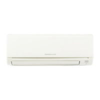
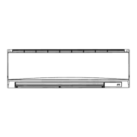
INDOOR UNIT
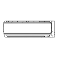
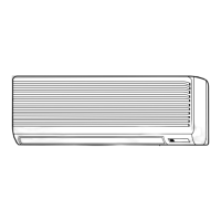
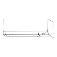
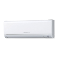
PKA-A12HA
PKA-A12HA
PKA-A18HA
PKA-A18HA
PKA-A12HAL
PKA-A12HAL
PKA-A18HAL
PKA-A18HAL
ON/OFF
TEMP.
COOL
DRY
AUTO
FAN
HEAT
3 3 2 2 3
WIRED REMOTE
CONTROLLER
WIRELESS REMOTE
CONTROLLER

Questions and Answers:

Mitsubishi Electric PKA-A18HA Specifications

General IconGeneral
BrandMitsubishi Electric
ModelPKA-A18HA
CategoryAir Conditioner
LanguageEnglish

Summary

SERVICE MANUAL

REFERENCE MANUAL

Outdoor Unit Service Manuals

Lists service manual references for outdoor units.

Technical Data Books

Lists data book references for outdoor units.

SAFETY PRECAUTIONS

General Safety Observations

Essential safety rules to follow before servicing.

Refrigerant R410A Handling Cautions

Specific precautions for using R410A refrigerant.

PART NAMES AND FUNCTIONS

Indoor Unit Components

Identification and labeling of indoor unit parts.

REMOTE CONTROLLER OPERATION

Wired Remote Controller Display and Buttons

Explanation of wired remote controller display and button functions.

Wireless Remote Controller Functions

Overview of features and indicators for the wireless remote controller.

SPECIFICATIONS

PKA-A12HA/PKA-A12HAL Specifications

Technical specifications for PKA-A12HA and PKA-A12HAL indoor units.

PKA-A18HA/PKA-A18HAL Specifications

Technical specifications for PKA-A18HA and PKA-A18HAL indoor units.

NOISE CRITERION CURVES

Noise Level Measurement

Presentation of noise criterion curves for different models.

OUTLINES AND DIMENSIONS

Indoor Unit Dimensions

Detailed dimensional drawings and measurements for the indoor units.

WIRING DIAGRAM

Indoor Unit Wiring Symbols and Connections

Explanation of symbols and diagram of internal wiring connections.

REFRIGERANT SYSTEM DIAGRAM

Refrigerant Flow and Component Identification

Diagram illustrating refrigerant circuit and sensor locations.

TROUBLESHOOTING

Error Code Diagnosis Overview

Summary of error code display and initial service actions.

Remote Controller Malfunction Diagnosis

Method to diagnose malfunctions using the remote controller.

Detailed Error Code Listings

Comprehensive lists of error codes for indoor and outdoor units.

Self-Diagnosis Action Table

Causes and countermeasures for specific error codes.

Troubleshooting Inferior Phenomena

Guidance for diagnosing issues based on observed symptoms.

Emergency Operation Procedures

Steps to activate and use emergency operation mode.

PART CHECK AND TESTING

Thermistor, Vane Motor, and Fan Motor Checks

Procedures for testing key internal components like thermistors and motors.

DC Fan Motor & Controller Board Testing

Detailed steps to check DC fan motor and its controller board.

TEST POINT DIAGRAM

Indoor Controller Board Test Points

Diagram showing test points on the indoor controller board for diagnostics.

CONFIGURATION SETTINGS

DIP Switch and Jumper Wire Functions

How to configure model, capacity, and pair settings using switches/wires.

SPECIAL FUNCTIONS

Rotation, Back-up, and 2nd Stage Cut-in Functions

Explains alternate unit operation, backup, and staged cooling.

Setting Special Functions via Remote

Procedure to set special functions using the wired remote controller.

DISASSEMBLY PROCEDURE

Basic Unit Component Removal

Steps for removing the front panel and lower unit side.

Electrical Components Removal

Instructions for removing electrical box, controller boards, and wiring.

Internal Mechanical Parts Removal

Steps for removing fan motor, vane motor, nozzle assembly, and drain hose.

Sensor and Heat Exchanger Removal

Procedures for removing thermistors and the heat exchanger.

Related product manuals