EasyManua.ls Logo

Mitsubishi Electric PKA-A12HA User Manual

Mitsubishi Electric PKA-A12HA
36 pages
To Next Page IconTo Next Page
Page #1 background imageLoading...
Page #1 background image
SERVICE MANUAL
SPLIT-TYPE, HEAT PUMP AIR CONDITIONERS
SPLIT-TYPE, AIR CONDITIONERS
NOTE:
• This manual describes
only service data of the
indoor units.
• RoHS compliant products
have <G> mark on the
spec name plate.
CONTENTS
1. REFERENCE MANUAL
...................................
2
2. SAFETY PRECAUTION
...................................
3
3. PART NAMES AND FUNCTIONS
...................
4
4. SPECIFICATIONS
............................................
7
5. NOISE CRITERION CURVES
..........................
8
6. OUTLINES AND DIMENSIONS
.......................
9
7. WIRING DIAGRAM
.........................................10
8. REFRIGERANT SYSTEM DIAGRAM
............
11
9. TROUBLESHOOTING
....................................
12
10. SPECIAL FUNCTION
.....................................
27
11. DISASSEMBLY PROCEDURE
.......................
30
Indoor unit
[Model names] [Service Ref.]
PARTS CATALOG (OCB456)
No. OCH456
March 2009
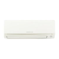
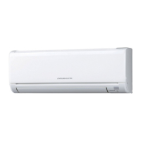
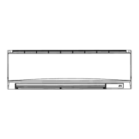
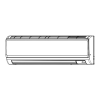
INDOOR UNIT
PKA-A12HA
PKA-A12HA
PKA-A18HA
PKA-A18HA
PKA-A12HAL
PKA-A12HAL
PKA-A18HAL
PKA-A18HAL
ON/OFF
TEMP.
COOL
DRY
AUTO
FAN
HEAT
3 3 2 2 3
WIRED REMOTE
CONTROLLER
WIRELESS REMOTE
CONTROLLER
Questions and Answers:

Mitsubishi Electric PKA-A12HA Specifications

General IconGeneral
BrandMitsubishi Electric
ModelPKA-A12HA
CategoryAir Conditioner
LanguageEnglish

Summary

Mitsubishi Electric Service Manual

Table of Contents

Lists all sections and their corresponding page numbers for easy navigation.

Reference Manual

Outdoor Unit Service Manual References

Lists service manual references for various outdoor unit models.

Technical Data Book References

Lists technical data book references for different outdoor unit series.

Safety Precautions

General Safety Rules

Essential safety guidelines to follow before starting any service work.

R410A Refrigerant Handling Cautions

Precautions for safe handling and use of R410A refrigerant.

Part Names and Functions

Indoor Unit Component Identification

Diagram and labels identifying parts of the indoor unit.

Service Tools for R410A

R410A Refrigerant Service Tool List

Lists and describes essential service tools required for R410A refrigerant.

Wired Remote Controller Operation

Wired Remote Controller Display Overview

Explains the various indicators and displays on the wired remote controller.

Wired Remote Controller Controls

Describes the functions of buttons on the wired remote controller for operation.

Wireless Remote Controller Operation

Wireless Remote Controller Display and Indicator Guide

Explains various displays and indicators on the wireless remote controller.

Wireless Remote Controller Buttons and Functions

Details the functions of all operational buttons on the wireless remote controller.

Unit Specifications

Indoor Unit Specifications (PKA-A12/A18)

Detailed technical specifications for PKA-A12HA, PKA-A12HAL, PKA-A18HA, PKA-A18HAL models.

Noise Criterion Curves

Noise Curves for PKA Series Models

Presents noise criterion curves for PKA-A12HA, PKA-A18HA, PKA-A12HAL, PKA-A18HAL models.

Noise Measurement Setup

Illustrates the setup for measuring noise levels of the unit.

Outlines and Dimensions

Dimensional Drawings for PKA Series

Provides detailed dimensional drawings and outlines for PKA series models.

Indoor Unit Installation Space Requirements

Specifies the necessary clearances and space for indoor unit installation.

Wiring Diagram

Wiring Diagram for PKA Series Units

Illustrates the electrical wiring connections for PKA series indoor units.

Wiring Diagram Symbols Explanation

Explains the symbols used in the wiring diagrams for clarity.

Wiring Diagram Service Notes

Provides important notes and cautions regarding wiring diagrams and connections.

Refrigerant System Diagram

Refrigerant Diagram for PKA Series

Illustrates the refrigerant flow and system components for PKA series units.

Condenser/Evaporator Thermistor (TH5) in Diagram

Shows the location and role of the TH5 thermistor in the refrigerant system.

Troubleshooting Guide

Troubleshooting Summary and Actions

Summarizes error code displays and recommended actions for service.

Self-Diagnosis Error Code Actions Summary

Provides a summary of actions for self-diagnosis error codes and reoccurring troubles.

Malfunction Diagnosis via Remote Controller

Diagnosis During Operation

Describes how to diagnose malfunctions when the unit is operating.

Diagnosis for Maintenance Service

Details the procedure for diagnosing malfunctions during maintenance service.

Error Code Reference

Indoor Unit Error Codes and Symptoms

Lists error codes, symptoms, and check codes for indoor unit detected errors.

Outdoor Unit Error Codes and Symptoms

Lists error codes, symptoms, and remarks for errors detected by other units.

Troubleshooting by Symptom

Troubleshooting: 'PLEASE WAIT' Message

Explains the 'PLEASE WAIT' message, its causes, and troubleshooting steps.

Troubleshooting: No Display Messages

Details symptoms where display messages do not appear upon power-on.

Indoor Controller LED1 Explanation

Describes the function of LED1, indicating microcomputer power status.

Indoor Controller LED2 Explanation

Describes the function of LED2, indicating remote controller power status.

Indoor Controller LED3 Explanation

Describes the function of LED3, indicating indoor/outdoor unit communication.

Self-Diagnosis Action Table

Error Code P1: Room Temperature Thermistor

Details cause and countermeasures for Room temperature thermistor (TH1) error.

Error Code P2: Pipe Temperature Thermistor

Details cause and countermeasures for Pipe temperature thermistor (TH2) error.

Error Code P4: Float Switch Connector

Details cause and countermeasures for Float switch connector (CN4F) error.

Error Code P5: Drain Overflow Protection

Details cause and countermeasures for Drain overflow protection operation.

Troubleshooting Error Codes (Part 1)

Error Code P6: Freezing/Overheating Protection

Details cause and countermeasures for freezing/overheating protection operations.

Error Code P8: Pipe Temperature Issues

Details cause and countermeasures for pipe temperature detection errors.

Troubleshooting Error Codes (Part 2)

Error Code P9: Condenser/Evaporator Thermistor

Details cause and countermeasures for Condenser/Evaporator thermistor (TH5) error.

Error Code PA: Forced Compressor Stop

Details cause and countermeasures for forced compressor stop due to water leakage.

Error Codes E0/E4: Remote Controller Transmission Error

Details cause and countermeasures for remote controller transmission/receiving errors.

Troubleshooting Error Codes (Part 3)

Error Codes E3/E5: Remote Controller Transmission Error

Details cause and countermeasures for remote controller transmission/receiving errors.

Error Code E6: Indoor/Outdoor Communication Error

Details cause and countermeasures for indoor/outdoor unit communication errors.

Error Code E7: Indoor/Outdoor Transmitting Error

Details cause and countermeasures for indoor/outdoor unit transmitting errors.

Error Code Fb: Indoor Controller Board Data Error

Details cause and countermeasures for errors reading indoor controller board data.

Error Codes E1/E2: Remote Controller Control Board Error

Details cause and countermeasures for remote controller control board errors.

Troubleshooting by Inferior Phenomena

Troubleshooting: LED2 Off on Indoor Board

Addresses symptoms where LED2 on the indoor controller board is off.

Troubleshooting Separate Power Supply Systems

Specific troubleshooting for units with separate indoor/outdoor power supplies.

Troubleshooting Common Phenomena

Troubleshooting: LED2 Blinking on Indoor Board

Addresses symptoms where LED2 on the indoor controller board is blinking.

Troubleshooting: Vane Performance Failure

Covers issues related to the upward/downward vane performance.

Troubleshooting: Wireless Remote Receiver

Addresses issues with the wireless remote controller receiver.

Emergency Operation Procedures

Emergency Operation: Wireless Remote Failure

Procedure for activating emergency operation when the wireless remote is unusable.

Emergency Operation: Wired Remote or Microcomputer Failure

Procedure for activating emergency operation when wired remote or microcomputer fails.

Parts Checking Procedures

Checking Room Temperature Thermistor (TH1)

Instructions for checking the resistance of the room temperature thermistor.

Checking Liquid Pipe Thermistor (TH2)

Instructions for checking the resistance of the liquid pipe thermistor.

Checking Condenser/Evaporator Thermistor (TH5)

Instructions for checking the resistance of the condenser/evaporator thermistor.

Checking Vane Motor (MV)

Instructions for checking the resistance of the vane motor.

Checking Fan Motor (MF)

Instructions for checking the fan motor, referring to section 9-6-2.

DC Fan Motor Check Methods

DC Fan Motor Self-Check Procedure

Step-by-step guide for self-checking the DC fan motor operation.

DC Fan Motor Wiring Contact Check

Procedure to check for contact failures in the fan motor wiring.

DC Fan Motor Power Supply Check

Procedure to measure voltage at the fan motor connector for power supply check.

DC Fan Motor Sensor Signal Check

Procedure to measure voltage for sensor signals of the DC fan motor.

Test Point Diagram

Indoor Controller Board Test Points

Diagram showing test points and connector locations on the indoor controller board.

CNMF Connector for Fan Motor

Details the CNMF connector and its test points for the fan motor.

CN3C Transmission Connector

Details the CN3C connector used for indoor/outdoor unit transmission.

DIP Switch and Jumper Wire Functions

DIP Switch SW1: Model Settings

Explains how to set the model using DIP switch SW1.

DIP Switch SW2: Capacity Settings

Explains how to set the capacity using DIP switch SW2.

Jumper Wires J41/J42: Pair Number Setting

Details setting the pair number for wireless remote controllers using jumper wires.

Special Functions

Rotation, Back-up, and 2nd Stage Cut-in Functions

Explains rotation, back-up, and 2nd stage cut-in functions for unit operation.

Rotation and Back-up Function Details

Details how main and sub units operate alternately for rotation and back-up.

2nd Stage Cut-in Function Details

Explains how a second unit starts operation based on demand and temperature.

Function Setting: Rotation

Rotation Setting Request Code List

Lists available request codes for configuring rotation and back-up functions.

2nd Stage Cut-in Setting Request Codes

Lists available request codes for configuring the 2nd stage cut-in function.

Setting Functions via Wired Remote Controller

Setting Functions: Stop Operation

The initial step of stopping the unit operation before setting functions.

Setting Functions: Enter Maintenance Mode

Procedure to press the TEST button to enter maintenance mode.

Setting Functions: Switch to Maintenance Monitor

Procedure to press the CHECK button to switch to maintenance monitor.

Setting Functions: Select Refrigerant Address

Procedure to select the desired refrigerant address using TEMP buttons.

Setting Functions: Set Request Code Number

Procedure to set the desired request code number using CLOCK buttons.

Setting Functions: Perform Function Setting

Procedure to press the FILTER button to finalize function setting.

Disassembly Procedures

Disassembly: Lower Indoor Unit Side

Step-by-step instructions for removing the lower side of the indoor unit.

Disassembly: Front Panel Removal

Instructions for removing the front panel of the indoor unit.

Component Removal Procedures (Part 1)

Disassembly: Indoor and Wireless Controller Boards

Instructions for removing the indoor controller and wireless controller boards.

Disassembly: Electrical Box Removal

Instructions for removing the electrical box from the unit.

Component Removal Procedures (Part 2)

Disassembly: Nozzle Assembly, Vane Motor, Drain Hose

Instructions for removing the nozzle assembly, vane motor, and drain hose.

Disassembly: Indoor Fan Motor and Line Flow Fan

Instructions for removing the indoor fan motor and the line flow fan.

Disassembly: Vane Motor Unit

Instructions for removing the vane motor unit and its components.

Component Removal Procedures (Part 3)

Disassembly: Pipe Thermistors

Instructions for removing the liquid pipe and condenser/evaporator thermistors.

Disassembly: Heat Exchanger Removal

Instructions for removing the heat exchanger from the unit.

Disassembly: Room Temperature Thermistor

Instructions for removing the room temperature thermistor.

Related product manuals