EasyManua.ls Logo

Mitsubishi Electric Mr. Slim PKA-A24KA4 User Manual

Mitsubishi Electric Mr. Slim PKA-A24KA4
32 pages
To Next Page IconTo Next Page
Page #1 background imageLoading...
Page #1 background image
SERVICE MANUAL
SPLIT-TYPE, HEAT PUMP AIR CONDITIONERS
SPLIT-TYPE, AIR CONDITIONERS
Note:
This manual describes only
service data of the indoor
units.
RoHS compliant products
have <G> mark on the spec
name plate.
CONTENTS
1. REFERENCE MANUAL
...................................
2
2. SAFETY PRECAUTION
...................................
3
3. PART NAMES AND FUNCTIONS
...................
4
4. SPECIFICATIONS
............................................
7
5. NOISE CRITERION CURVES
..........................
8
6. OUTLINES AND DIMENSIONS
.......................
9
7. WIRING DIAGRAM
.........................................
10
8. REFRIGERANT SYSTEM DIAGRAM
............
11
9. TROUBLESHOOTING
....................................
12
10. SPECIAL FUNCTION
.....................................
26
11. DISASSEMBLY PROCEDURE
.......................
29
PARTS CATALOG (OCB488)
No. OCH488
REVISED EDITION-A
May 2011
ON/OFF
TEMP.
9700058
WIRED REMOTE
CONTROLLER
(Option)
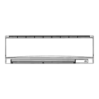
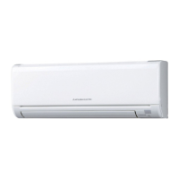
INDOOR UNIT
Indoor unit
[Model names] [Service Ref.]
PKA-A24KA4
PKA-A24KA4.TH
PKA-A30KA4
PKA-A30KA4.TH
PKA-A36KA4
PKA-A36KA4.TH
IR WIRELESS REMOTE
CONTROLLER
(Option)
ON/OFF TEMP
Revision:
6. OUTLINES AND
DIMENSIONS has been modi-
fied in REVISED EDITION-A.
Some descriptions have been
modified.
Please void OCH488.

Questions and Answers:

Mitsubishi Electric Mr. Slim PKA-A24KA4 Specifications

General IconGeneral
BrandMitsubishi Electric
ModelMr. Slim PKA-A24KA4
CategoryAir Conditioner
LanguageEnglish

Summary

Reference Manual

Outdoor Unit Service Manual

Details service information for outdoor units related to the PKA series.

Remote Controller Options

Overview of optional remote controller types: RF thermostat, Wired, and IR wireless.

Safety Precautions

General Safety Observance

Mandatory disconnection of all supply circuits before accessing terminals.

Cautions for New Refrigerant (R410A)

Guidelines for handling R410A refrigerant, including piping, tools, and charging.

Additional Refrigerant Charge Procedure

Service Tools for R410A

Lists exclusive service tools required for R410A refrigerant handling.

Part Names and Functions

Indoor Unit Components

Identifies key parts of the indoor unit like front grille, filter, air outlet, and emergency switch.

Wired Remote Controller Features

Wired Remote Controller Operation

Details the function of buttons like temperature, mode, timer, and fan speed controls.

IR Wireless Remote Controller Features

IR Wireless Remote Controller Operation

Details functions like operation mode, timer settings, fan speed, and louver control.

Specifications

PKA-A24KA4.TH Specifications

Technical details including power supply, airflow, noise level, and dimensions for PKA-A24KA4.TH.

PKA-A30KA4.TH Specifications

Technical details including power supply, airflow, noise level, and dimensions for PKA-A30KA4.TH.

PKA-A36KA4.TH Specifications

Technical details including power supply, airflow, noise level, and dimensions for PKA-A36KA4.TH.

Noise Criterion Curves

Noise Curves for PKA-A24KA4/A30KA4

Octave band sound pressure levels for PKA-A24KA4.TH and PKA-A30KA4.TH.

Noise Curves for PKA-A36KA4.TH

Octave band sound pressure levels for PKA-A36KA4.TH.

Outlines and Dimensions

Unit Dimensions and Piping

Detailed dimensions, piping connections, and installation clearances for PKA series indoor units.

Wiring Diagram

Indoor Unit Wiring Schematics

Wiring diagrams for PKA series indoor units, including component connections and tables.

Refrigerant System Diagram

Refrigerant Circuit Components

Diagram showing heat exchanger, strainers, distributor, and thermistors in the refrigerant circuit.

Troubleshooting Guide

Troubleshooting Summary

Summary of error code display, actions for reoccurring or non-reoccurring troubles.

Malfunction Diagnosis via Remote Controller

Indoor Unit Error Codes

Outdoor Unit and Other Error Codes

Lists error codes detected by the outdoor unit and their symptoms.

LED Indicators and Troubleshooting Causes

Self-Diagnosis Action Table

Error Code P1: Room Temperature Thermistor

Details causes and countermeasures for P1 error related to the room temperature thermistor (TH1).

Error Code P2: Pipe Temperature Thermistor

Details causes and countermeasures for P2 error related to the pipe temperature thermistor (TH2).

Error Code P4: Drain Float Switch

Details causes and countermeasures for P4 error related to the drain float switch.

Error Code P5: Drain Overflow Protection

Details causes and countermeasures for P5 error related to drain overflow protection.

Error Code P6: Freezing/Overheating Protection

Error Code P8: Pipe Temperature

Details causes and countermeasures for P8 error related to pipe temperature in cooling/heating modes.

Error Code P9: Pipe Temperature Thermistor (TH5)

Error Code PA: Forced Compressor Stop

Details causes and countermeasures for PA error regarding forced compressor stop due to water leakage.

Error Codes E0/E4: Remote Controller Errors

Details causes and countermeasures for E0/E4 errors related to remote controller transmission or signal reception.

Error Codes E3/E5: Remote Controller Transmission Error

Error Code E6: Indoor/Outdoor Communication Error (Signal)

Details causes and countermeasures for E6 error related to signal reception between indoor/outdoor units.

Error Codes E7/Fb: Communication Error (Transmit)

Details causes and countermeasures for E7/Fb errors related to transmitting signals between units.

Error Codes E1/E2: Remote Controller Control Board

Details causes and countermeasures for E1/E2 errors related to the remote controller's control board.

Troubleshooting by Inferior Phenomena

Vane Performance Issues

Addresses issues with upward/downward vane movement, rotation, or fixed position.

IR Wireless Remote Receiver Issues

Troubleshooting for weak batteries, connector contact failures, and board connections for the IR receiver.

Special Functions

Emergency Operation Modes

Procedures for emergency operation when remote controllers fail or are exhausted.

Emergency Operation (IR Remote Failure)

How to use emergency buttons on the indoor unit when the IR wireless remote controller is unavailable.

Emergency Operation (Wired Remote/Microprocessor Failure)

Activating emergency operation via the indoor controller board switch (SWE) when wired remote or microprocessor fails.

Part Inspection Procedures

Thermistor Checks

Methods to check room, pipe, and condenser/evaporator thermistors for normal or abnormal resistance.

DC Fan Motor Checks

Test Point Diagram

Indoor Controller Board Test Points

Diagram showing test points for fan motor, terminal blocks, and various sensors on the indoor controller board.

DIP Switch and Jumper Wire Functions

Jumper Wire Settings

Explains functions and settings for jumper wires J41, J42, and JP3 related to remote controllers and board type.

Rotation and Back-Up Functions

2nd Stage Cut-In Function

Enables a second unit to start operation when the first unit cannot meet high-demand conditions.

Setting Rotation and Cut-In Functions

Wired Remote Controller Function Settings

Back-Up Heating Function

How the back-up heater signal is sent based on temperature difference during heating operation.

Back-Up Heating Operation

Explains how the back-up heater signal is sent based on temperature difference during heating operation.

Back-Up Heating Connection

Details the connection requirements for the back-up heating function using PAC-SE59RA-E.

Disassembly Procedure

Removing the Front Panel

Step-by-step instructions for removing the front grille, panel, and corner box.

Removing Controller Boards

Instructions for removing the indoor controller board and the IR wireless remote controller board.

Removing the Electrical Box

Removing Nozzle Assembly and Drain Hose

Instructions for removing the nozzle assembly, vane motor connector, and drain hose.

Removing the Vane Motor

Steps to remove the vane motor unit cover, vane motor unit, and the vane motor itself.

Removing Fan Motor and Line Flow Fan

Removing Pipe Thermistors

Procedure to remove the liquid pipe thermistor and the condenser/evaporator pipe thermistor.

Removing the Heat Exchanger

Removing Room Temperature Thermistor

Procedure to remove the room temperature thermistor (TH1) and disconnect its connector.

Related product manuals