Do you have a question about the Mitsubishi Electric Mr. Slim PKA-A24KA and is the answer not in the manual?
| Brand | Mitsubishi Electric |
|---|---|
| Model | Mr. Slim PKA-A24KA |
| Category | Air Conditioner |
| Language | English |
Lists service manuals for outdoor units and their corresponding reference numbers.
Lists technical data books for specific outdoor unit series.
Emphasizes disconnecting all supply circuits before accessing terminals.
Provides guidelines for using R410A refrigerant, including pipe preparation, oil types, charging, and tools.
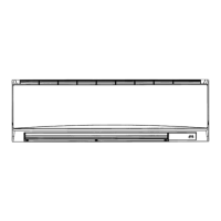
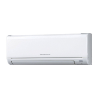
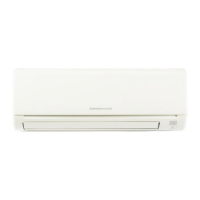
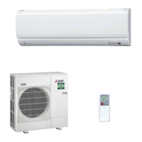
Identifies key parts of the indoor unit, including the front grille, filter, air inlet, and louvers.
Explains the display elements and operation buttons of the wired remote controller.
Details the display indicators and operational buttons of the wireless remote controller.
Lists detailed specifications for PKA-A24, PKA-A30, and PKA-A36 indoor units.
Presents octave band sound pressure levels and corresponding NC curves for different models.
Provides detailed dimensional drawings and measurements for the indoor units.
Illustrates the electrical connections and component layout for the indoor unit.
Depicts the refrigerant flow path and includes component locations like heat exchangers and strainers.
Outlines general actions for recurring and non-recurring troubles based on error code display.
Provides a step-by-step procedure for diagnosing malfunctions using the remote controller.
Details error codes, causes, and countermeasures for common unit malfunctions.
Addresses troubleshooting based on observed phenomena like LED status or vane performance.
Explains how to activate emergency operation when remote controllers fail or are unavailable.
Details methods for checking the resistance and condition of key internal components.
Illustrates test points on the indoor controller board for voltage and signal checks.
Explains the functions and settings of DIP switches and jumper wires on the control PC board.
Describes how main and sub units operate alternately and provide backup functionality.
Explains the function where a second unit starts operation when capacity is insufficient.
Details the procedure for setting rotation and 2nd stage cut-in functions using the wired remote controller.
Describes the operation of the back-up heater based on temperature differences.
Details how to remove the front grille, panel, and corner box from the indoor unit.
Explains the process of removing the indoor controller board and wireless remote controller board.
Covers the removal of the electrical box, nozzle assembly, and drain hose.
Provides steps for removing the vane motor from its unit.
Details the procedure for removing the indoor fan motor and the line flow fan.
Explains how to remove the liquid pipe and condenser/evaporator thermistors.
Covers the removal of the heat exchanger and the room temperature thermistor.
Illustrates the panel and heat exchanger components with numbered parts for identification.
Lists part numbers, names, and specifications for panel and heat exchanger components.
Displays an illustration of various functional parts with numerical labels for identification.
Lists part numbers, names, and specifications for functional components like motors, boards, and remotes.