EasyManua.ls Logo

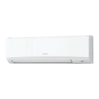
Mitsubishi Electric Mr. Slim PKA-A30KA4 User Manual

Mitsubishi Electric Mr. Slim PKA-A30KA4
32 pages
To Next Page IconTo Next Page
Page #1 background imageLoading...
Page #1 background image
SERVICE MANUAL
SPLIT-TYPE, HEAT PUMP AIR CONDITIONERS
SPLIT-TYPE, AIR CONDITIONERS
Note:
This manual describes only
service data of the indoor
units.
RoHS compliant products
have <G> mark on the spec
name plate.
CONTENTS
1. REFERENCE MANUAL
...................................
2
2. SAFETY PRECAUTION
...................................
3
3. PART NAMES AND FUNCTIONS
...................
4
4. SPECIFICATIONS
............................................
7
5. NOISE CRITERION CURVES
..........................
8
6. OUTLINES AND DIMENSIONS
.......................
9
7. WIRING DIAGRAM
.........................................
10
8. REFRIGERANT SYSTEM DIAGRAM
............
11
9. TROUBLESHOOTING
....................................
12
10. SPECIAL FUNCTION
.....................................
26
11. DISASSEMBLY PROCEDURE
.......................
29
PARTS CATALOG (OCB488)
No. OCH488
REVISED EDITION-A
May 2011
ON/OFF
TEMP.
9700058
WIRED REMOTE
CONTROLLER
(Option)
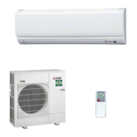
INDOOR UNIT
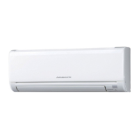
Indoor unit
[Model names] [Service Ref.]
PKA-A24KA4
PKA-A24KA4.TH
PKA-A30KA4
PKA-A30KA4.TH
PKA-A36KA4
PKA-A36KA4.TH
IR WIRELESS REMOTE
CONTROLLER
(Option)
ON/OFF TEMP
Revision:
6. OUTLINES AND
DIMENSIONS has been modi-
fied in REVISED EDITION-A.
Some descriptions have been
modified.
Please void OCH488.

Questions and Answers:

Mitsubishi Electric Mr. Slim PKA-A30KA4 Specifications

General IconGeneral
BrandMitsubishi Electric
ModelMr. Slim PKA-A30KA4
CategoryAir Conditioner
LanguageEnglish

Summary

MITSUBISHI ELECTRIC SERVICE MANUAL

REFERENCE MANUAL

Provides general information and references for the service manual, including remote controller details.

SAFETY PRECAUTIONS

Details essential safety guidelines and warnings for servicing units utilizing R410A refrigerant.

PART NAMES AND FUNCTIONS

Identifies and describes the components and operational roles of the indoor unit.

SPECIFICATIONS

Lists the technical specifications for the PKA-A24KA4, PKA-A30KA4, and PKA-A36KA4 indoor units.

NOISE CRITERION CURVES

Presents noise level data across different frequency bands for the PKA-A24KA4, PKA-A30KA4, and PKA-A36KA4 models.

OUTLINES AND DIMENSIONS

Provides detailed physical dimensions, piping connections, and external views of the indoor units.

WIRING DIAGRAM

Illustrates the electrical connections and wiring schematics for the indoor unit and optional parts.

REFRIGERANT SYSTEM DIAGRAM

Depicts the flow and components of the refrigerant system within the unit, including thermistor locations.

TROUBLESHOOTING

Offers guidance for diagnosing and resolving common operational issues, error codes, and malfunctions.

MALFUNCTION-DIAGNOSIS METHOD BY REMOTE CONTROLLER

Details procedures for diagnosing unit malfunctions using IR wireless and wired remote controllers.

SELF-DIAGNOSIS ACTION TABLE

Provides a table correlating error codes with causes and countermeasures for unit malfunctions.

TROUBLESHOOTING BY INFERIOR PHENOMENA

Addresses specific operational issues like vane performance and remote controller receiver problems.

EMERGENCY OPERATION

Explains how to perform emergency operation when remote controllers fail or are exhausted.

HOW TO CHECK THE PARTS

Provides methods for checking the functionality of key components like thermistors and motors.

TEST POINT DIAGRAM

Illustrates test points on the indoor controller board for diagnosing electrical issues.

FUNCTIONS OF DIP SWITCH AND JUMPER WIRE

Details the functions controlled by dip switches and jumper wires on the indoor control PC board.

SPECIAL FUNCTION

Explains advanced features like rotation function and back-up heating.

Rotation Function (and back-up function, 2nd stage cut-in function)

Details operation and setting methods for rotation and second stage cut-in functions with wired remote controllers.

BACK-UP HEATING FUNCTION (CN152)

Explains the operation and connection requirements for the back-up heating function.

DISASSEMBLY PROCEDURE

Provides step-by-step instructions for dismantling the indoor unit for maintenance and repair.

REMOVING THE PANEL

Instructions for safely removing the front panel and corner box of the indoor unit.

REMOVING THE INDOOR CONTROLLER BOARD AND THE WIRELESS CONTROLLER BOARD

Guides on how to remove the indoor controller board and the IR wireless remote controller board.

REMOVING THE ELECTRICAL BOX

Procedure for removing the electrical box assembly from the indoor unit.

REMOVING THE NOZZLE ASSEMBLY (with VANE and VANE MOTOR) AND DRAIN HOSE

Steps for removing the nozzle assembly, vane motor, and drain hose.

REMOVING THE VANE MOTOR

Detailed instructions for removing the vane motor unit and the vane motor itself.

REMOVING THE INDOOR FAN MOTOR AND THE LINE FLOW FAN

Procedure for removing the indoor fan motor, motor bed, and line flow fan.

REMOVING THE LIQUID PIPE THERMISTOR AND COND / EVA PIPE THERMISTOR

Instructions for removing the liquid pipe and condenser/evaporator pipe thermistors.

REMOVING THE HEAT EXCHANGER

Steps for safely removing the heat exchanger from the indoor unit.

REMOVING THE ROOM TEMPERATURE THERMISTOR

Procedure for removing the room temperature thermistor and its connector.

Related product manuals