EasyManua.ls Logo

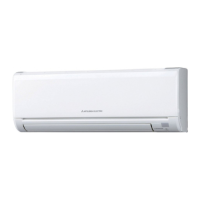
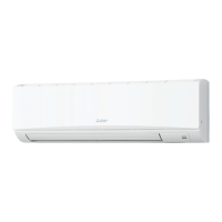
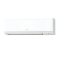
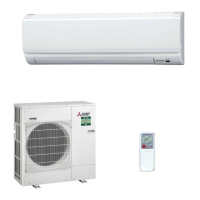
Mitsubishi Electric Mr.Slim PKA-M35HA User Manual

Mitsubishi Electric Mr.Slim PKA-M35HA
42 pages
To Next Page IconTo Next Page
Page #1 background imageLoading...
Page #1 background image
SERVICE MANUAL
Notes:
This manual describes
service data of the
indoor units only.
RoHS compliant prod-
ucts have <G> mark on
the spec name plate.
CONTENTS
1. REFERENCE MANUAL
...................................
2
2. SAFETY PRECAUTION
...................................
3
3. PARTS NAMES AND FUNCTIONS
.................
8
4. SPECIFICATIONS
...........................................
12
5. NOISE CRITERION CURVES
.........................
13
6. OUTLINES AND DIMENSIONS
......................
14
7. WIRING DIAGRAM
.........................................
15
8. REFRIGERANT SYSTEM DIAGRAM
............
17
9. TROUBLESHOOTING
....................................
18
10. FUNCTION SETTING
....................................
34
11. SPECIAL FUNCTION
.....................................
35
12. DISASSEMBLY PROCEDURE
.......................
37
Indoor unit
[Model Name] [Service Ref.]
PARTS CATALOG (OCB660)
INDOOR UNIT
PKA-M35HA
PKA-M35HA
PKA-M50HA
PKA-M50HA
PKA-M35HAL
PKA-M35HAL
PKA-M50HAL
PKA-M50HAL
SPLIT-TYPE, HEAT PUMP AIR CONDITIONERS
SPLIT-TYPE, AIR CONDITIONERS
No. OCH660
March 2017
R32/R410A
Questions and Answers:

Mitsubishi Electric Mr.Slim PKA-M35HA Specifications

General IconGeneral
SeriesMr. Slim
Cooling Capacity3.5 kW
Heating Capacity4.0 kW
Power Supply220-240 V, 50 Hz
RefrigerantR410A
Indoor Unit Weight9 kg
TypeWall Mounted
Operating Temperature (Cooling)-10 to +46 °C
Operating Temperature (Heating)-15 to +24 °C

Summary

REFERENCE MANUAL

SAFETY PRECAUTION

MEANINGS OF SYMBOLS DISPLAYED ON THE UNIT

Explains symbols used on the unit for safety information.

ALWAYS OBSERVE FOR SAFETY

Emphasizes general safety practices before performing service.

CAUTIONS RELATED TO NEW REFRIGERANT

Provides specific precautions for handling R32/R410A refrigerants.

SAFETY PRECAUTION

Warning for Service

Lists critical warnings for service personnel to prevent hazards.

Cautions for Service

Details important cautions to follow during maintenance and repair.

Additional Refrigerant Charge

Instructions for correctly charging refrigerant from a cylinder.

SAFETY PRECAUTION

Cautions for Unit Using R32 Refrigerant

Specific safety guidelines for units utilizing R32 refrigerant.

SAFETY PRECAUTION

Service Tools

Lists essential tools required for servicing R32/R410A refrigerant units.

PARTS NAMES AND FUNCTIONS

Indoor Unit

Identifies and describes the components of the indoor unit.

PARTS NAMES AND FUNCTIONS

Wireless Remote Controller (Option for HA Model)

Details the functions and displays of the wireless remote controller.

PARTS NAMES AND FUNCTIONS

Wired Remote Controller (Option)

Explains the interface and functions of the wired remote controller.

PARTS NAMES AND FUNCTIONS

Menu Structure

Outlines the navigation and options available in the wired remote controller menu.

SPECIFICATIONS

NOISE CRITERION CURVES

SOUND LEVELS

Presents sound pressure levels measured in an anechoic room.

NOISE CRITERION CURVES

Illustrates noise levels across different frequency bands.

OUTLINES AND DIMENSIONS

WIRING DIAGRAM

REFRIGERANT SYSTEM DIAGRAM

TROUBLESHOOTING

TROUBLESHOOTING

General approach to troubleshooting and identifying issues.

MALFUNCTION-DIAGNOSIS METHOD BY REMOTE CONTROLLER

Procedure for diagnosing malfunctions using the remote controller.

TROUBLESHOOTING

SELF-DIAGNOSIS ACTION TABLE

Lists error codes and corresponding causes/countermeasures.

TROUBLESHOOTING

TROUBLESHOOTING BY INFERIOR PHENOMENA

Troubleshooting based on observed symptoms rather than error codes.

TROUBLESHOOTING

EMERGENCY OPERATION

Instructions for operating the unit in emergency mode when controls fail.

TROUBLESHOOTING

HOW TO CHECK THE PARTS

Guide to inspecting and testing specific components for faults.

TROUBLESHOOTING

TEST POINT DIAGRAM

Illustrates test points on the indoor controller board for diagnostics.

TROUBLESHOOTING

FUNCTIONS OF DIP SWITCH AND JUMPER WIRE

Explains how DIP switches and jumper wires configure unit functions.

FUNCTION SETTING

UNIT FUNCTION SETTING BY THE REMOTE CONTROLLER

Details how to set various unit functions using the remote controller.

SPECIAL FUNCTION

ROTATION FUNCTION (AND BACK-UP FUNCTION, 2ND STAGE CUT-IN FUNCTION)

Describes functions for alternating unit operation and capacity enhancement.

SPECIAL FUNCTION

How to set rotation function (Back-Up function, 2nd stage cut-in function)

Instructions for setting rotation and cut-in functions via wired remote controller.

DISASSEMBLY PROCEDURE

Related product manuals