Do you have a question about the Mitsubishi Electric PKFY-P63VKM-E.TH and is the answer not in the manual?
| Brand | Mitsubishi Electric |
|---|---|
| Model | PKFY-P63VKM-E.TH |
| Category | Air Conditioner |
| Language | English |
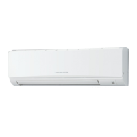
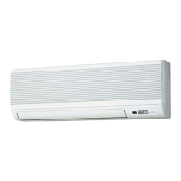
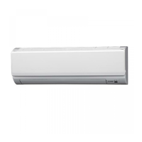
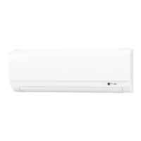
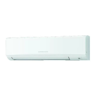
Service manual for Mitsubishi Electric PKFY Series Wall Mounted air conditioners.
Safety guidelines for using R407C refrigerant, including piping and oil.
Essential service procedures and warnings related to refrigerant recovery and charging.
Steps and diagram for recharging refrigerant, emphasizing liquid charging.
List of essential tools required for servicing R407C refrigerant systems.
Safety guidelines for R410A refrigerant, including piping, oil, and charging methods.
Key service steps for R410A units, including refrigerant recovery and filter drier use.
Procedure for charging additional refrigerant for R410A units, emphasizing cylinder orientation.
List of specialized tools required for servicing R410A refrigerant systems.
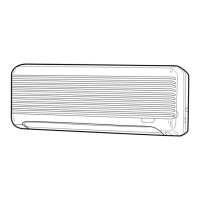
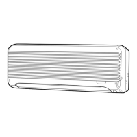
Identification and description of the various parts of the indoor unit.
Detailed explanation of the wired remote controller's display and operation sections.
Explanation of indicators and displays on the wired remote controller.
Description of buttons and controls in the wired remote controller's operation section.
Details on the wireless remote controller's display, buttons, and operational functions.
Explanation of various display indicators and symbols on the wireless remote controller.
Description of the functions of various buttons on the wireless remote controller.
Detailed technical specifications for PKFY-P63VKM-E and PKFY-P100VKM-E models.
Specifications for electrical components and parts of the indoor units.
Sound level measurements for the indoor units in an anechoic room.
Noise criteria curves for PKFY-P63VKM-E and PKFY-P100VKM-E models.
Detailed diagrams showing dimensions, piping connections, and knockout holes.
Specifications for the minimum clearance required around the indoor unit.
Schematic of the indoor unit's wiring, including component symbols and connections.
Explanation of LED indicators on the indoor controller board for service purposes.
Diagram illustrating the refrigerant flow and location of key components.
Procedures for testing thermistors, motors, and the linear expansion valve.
Graph showing resistance vs. temperature for thermistors and characteristic formula.
Explanation of the linear expansion valve's operation and connection to the controller board.
Details on output pulse signals, valve operation, and noise troubleshooting.
Diagnosing and resolving issues like processor failure, locked valves, and connection problems.
Procedure for diagnosing and fixing issues with the DC fan motor and controller.
Step-by-step guide to diagnose fan motor problems, including wiring, power, and sensor checks.
Detailed explanation of dip switch functions for mode, capacity, model, and address settings.
Procedure for setting the pair number for wireless remote controllers with multiple indoor units.
Diagram showing test points and connections on the indoor controller board.
Diagram showing test points and connections on the wireless remote controller board.
Diagram showing test points and connections on the address board.
Step-by-step instructions for removing the front panel and corner box.
Instructions for removing the address board, controller board, and electrical covers.
Steps to remove the electrical box, including wiring and covers.
Procedure for removing the nozzle assembly, vane motor, and drain hose.
Detailed steps for disassembling and removing the vane motor unit.
Instructions for removing the indoor fan motor and line flow fan assembly.
Steps for removing the liquid and gas pipe thermistors.
Procedure for removing the heat exchanger and linear expansion valve (LEV).
Steps to remove the room temperature thermistor (TH21).