EasyManua.ls Logo

Mitsubishi Electric PL18FK2 User Manual

Mitsubishi Electric PL18FK2
140 pages
To Next Page IconTo Next Page
Page #1 background imageLoading...
Page #1 background image
SERVICE
&
PARTS
MANUAL
1
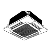
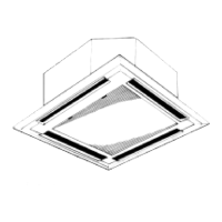
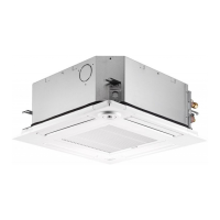
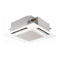
Series PL] Ceiling Cassettes
~0d-l~
PL18FK2/PU18EK, PU1 8EK-I
PL24FK2/PU24EK, PU24EK-I
PL30FK2/PU30EK, PU30EK-I
PL36FK2/PU36EK,PU36EK-i
PL42FK21PU42EK2, PU42EK2-I
-1
Ceiling Cassettes
PLL12FK/PUL12EKJPUL1 2EK-I
PLLl8FK/PUL18EK, PULl 8EK-I
PLL24FK/PUL24EK, PUL24EK-I
Ceiling Suspended
I
Series PC
L
1
Ceiling Suspended
WKI
Wall
Mounted
PKI 8EK/PU18EK,PUI 8EK-I
PK24EK/PU24EK,PU24EK-l
PK30EK/PU30EK, PU30EK-I
Wall
Mounted
PKLI 2EK/PUL12EK, PULl 2EK-I
PKLI 8EK/PUL18EK, PULl 8EK-I
PKL24EK/PUL24EK, PUL24EK-I
@
The
Slim Line.
fof
PU18EK
I
and
PUL18EK-I
Question and Answer IconNeed help?

Do you have a question about the Mitsubishi Electric PL18FK2 and is the answer not in the manual?

Mitsubishi Electric PL18FK2 Specifications

General IconGeneral
BrandMitsubishi Electric
ModelPL18FK2
CategoryAir Conditioner
LanguageEnglish

Summary

3 SPECIFICATIONS

4 DATA

1. Performance Data

Detailed performance specifications including cooling capacity and corrections.

5 OUTLINES AND DIMENSIONS

6 REFRIGERANT SYSTEM DIAGRAM

7 WIRING DIAGRAM

8 OPERATION FLOW-CHART

9 OUTLINE OF MICROPROCESSOR CONTROL

2. Cooling Operation

Details the cooling operation modes and functions of the microprocessor.

6. Test Run Function

Guides on performing test run operations for diagnostics and setup.

7. Emergency Operation

Describes how to operate the unit in emergency cooling mode.

8. Dip Switch Functions

Describes the functions of DIP switches for configuration and operation.

9. Outdoor Microprocessor Control

Explains the control functions of the outdoor unit microprocessor.

10 TROUBLE SHOOTING

1. Remote Controller Display Abnormality

Addresses issues with remote controller display, errors, and no display.

2. Self-Diagnostic Function with Remote Controller

Explains how to use the self-diagnostic function and interpret check codes.

3. Self-Diagnostic Function with LED on Outdoor Controller Board

Details using LEDs on the outdoor board for self-diagnosis and troubleshooting.

4. Troubleshooting According to Check Code

Lists check codes, their causes, and troubleshooting steps.

5. When Outdoor Unit Does Not Work

Provides troubleshooting steps when the outdoor unit fails to operate.

6. Wrong Wiring on Site

Identifies issues and phenomena related to incorrect wiring on site.

7. Other Troubles and Causes

Covers general troubleshooting for other common issues and their causes.

14 DISASSEMBLY PROCEDURE

15 OPTIONAL PARTS

Related product manuals