EasyManua.ls Logo

Mitsubishi Electric PLH-4GKSB1.UK User Manual

Mitsubishi Electric PLH-4GKSB1.UK
84 pages
To Next Page IconTo Next Page
Page #1 background imageLoading...
Page #1 background image
TECHNICAL & SERVICE MANUAL
SPLIT-TYPE,HEAT PUMP AIR CONDITIONERS
CONTENTS
1. FEATURES ···········································3
2. PART NAMES AND FUNCTIONS········5
3. SPECIFICATIONS·································7
4. DATA ···················································11
5. OUTLINES AND DIMENSIONS··········15
6. WIRING DIAGRAM·····························18
7.
REFRIGERANT SYSTEM DIAGRAM
······19
8. OPERATION FLOW-CHART··············20
9. MICROPROCESSOR CONTROL·······24
10. TROUBLESHOOTING························47
11. 4-WAY AIR FLOW SYSTEM···············55
12. SYSTEM CONTROL···························60
13. DISASSEMBLY PROCEDURE···········65
14. PARTS LIST········································68
15. OPTIONAL PARTS ·····························78
[Model names]
PLH-3GK(H)B
PLH-4GK(H)SB
PLH-5GK(H)SB
PLH-6GK(H)SB
No. OC148
1997
This manual does not cover the following
outdoor units. When servicing them,
please refer to the service manual
No.OC150 and this manual in a set.
[Service Ref.]
PUH-3YKA2.UK
PUH-3VKA2.UK
PUH-4YKSA2.UK
PUH-5YKSA2.UK
PUH-6YKSA2.UK
INDOOR UNIT
Ceiling Cassettes
Series PLH
FILTER
CHECK MODE
TEST RUN
REMOTE CONTROLLER
The Slim Line.
From Mitsubishi Electric.
[Service Ref.]
PLH-3GK(H)B
1
.UK
PLH-4GK(H)SB
1
.UK
PLH-5GK(H)SB
1
.UK
PLH-6GK(H)SB
1
.UK
Question and Answer IconNeed help?

Do you have a question about the Mitsubishi Electric PLH-4GKSB1.UK and is the answer not in the manual?

Mitsubishi Electric PLH-4GKSB1.UK Specifications

General IconGeneral
Energy Efficiency Class (Cooling)A++
Energy Efficiency Class (Heating)A+
Indoor Unit Noise Level21 dB(A)
Power Supply220-240V, 50Hz
Noise Level (Outdoor Unit)50 dB(A)
RefrigerantR32

Summary

FEATURES

PART NAMES AND FUNCTIONS

Indoor Unit and Remote Controller Components

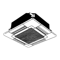
Identifies key parts of the indoor unit and the remote controller.

SPECIFICATIONS

Technical Specifications for Indoor and Outdoor Units

Provides detailed technical data for unit performance and dimensions.

PERFORMANCE DATA

Cooling, Heating Capacities, and Correction Factors

Presents performance data including capacities and factors affecting performance.

ELECTRICAL DATA

Electrical Specifications by Power Supply Configuration

Lists electrical data based on voltage and phase configurations.

OUTLINES AND DIMENSIONS

WIRING DIAGRAM

System Electrical Wiring Schematics

Illustrates the electrical connections for the entire system.

REFRIGERANT SYSTEM DIAGRAM

Refrigerant Circuit and Component Flow

Shows the path of refrigerant through the system components.

OPERATION FLOW-CHARTS

MICROPROCESSOR CONTROL SYSTEM

INDOOR UNIT CONTROL MODES

EMERGENCY OPERATION

DIP SWITCH FUNCTIONS

OUTDOOR UNIT CONTROL

TROUBLESHOOTING

Test Run Issues and Self-Diagnostic Functions

Guides on troubleshooting common issues during test runs and using self-diagnostics.

MALFUNCTION CHECK CODES

Error Codes, Diagnosis, and Resolution Steps

Lists error codes and specific steps for diagnosing and resolving them.

TROUBLESHOOTING BY CHECK CODE

Specific Check Code Troubleshooting

Details troubleshooting steps based on specific blinking LED check codes.

WRONG WIRING ON SITE

Wiring Errors and Their Consequences

Identifies common wiring mistakes and their effects on unit operation.

4-WAY AIR FLOW SYSTEM

SYSTEM CONTROL OPTIONS

GROUP CONTROL WITH SINGLE REMOTE

REMOTE CONTROL CONFIGURATIONS

DISASSEMBLY PROCEDURE

CENTRALIZED REMOTE CONTROLLER

Related product manuals