Do you have a question about the Mitsubishi Electric PU-P100YHA and is the answer not in the manual?
| Cooling Capacity | 10.0 kW |
|---|---|
| Heating Capacity | 11.2 kW |
| Refrigerant | R410A |
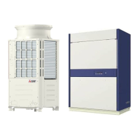
| Indoor Unit Weight | 15 kg |
| Type | Split System |
| Power Supply | 380-415V, 50Hz |
| Indoor Unit Dimensions (WxHxD) | 1100 x 325 x 238 mm |
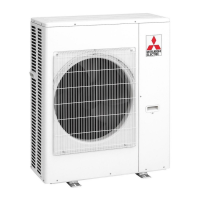
| Outdoor Unit Noise Level | 53 dB(A) |
| Outdoor Unit Dimensions (WxHxD) | 950 x 1380 x 370 mm |
Thermistor replaced from discharge temp to compressor surface temp.
Fan grille component has been modified.
Modification to structural parts, e.g., Munsell color change.
Outdoor controller board (O.B) has been updated or changed.
Lists model names and corresponding service manual references for indoor units.
Provides the manual number for technical data.
Disconnect all supply circuits before accessing terminals.
Cautions for using R410A refrigerant, including piping, tools, and handling.
Pre-charged refrigerant supplied for shipment, improving quality and installation speed.
Technical details for outdoor units including power, compressor, fan, and dimensions.
Details on pipe size, connection method, and piping length limits.
Table of refrigerant charge (kg) based on piping length.
Winding resistance data for different compressor models.
Octave band sound pressure levels for cooling and heating modes.
Performance data for cooling mode, including capacity, input, and various temperatures/pressures.
Diagrams showing overall dimensions, service space, and foundation bolts.
Details on how piping and wiring connections are made from different directions.
Schematic showing electrical connections and a list of symbols used.
Power wiring specifications including wire size and circuit rating.
Wiring diagrams for synchronized twin and triple systems.
Wiring patterns for single indoor/outdoor unit systems.
Wiring patterns for multi-unit systems with separate power supplies.
Details on cross-section, wire size, number of wires, polarity, and length.
Guidelines for M-NET wiring to prevent noise and ensure proper grounding.
How to set M-NET addresses using rotary switches on the outdoor unit.
How to set refrigerant addresses using DIP switches on the outdoor controller board.
Rules for setting addresses in multi-grouping systems to avoid conflicts.
Schematics illustrating refrigerant flow for different models and modes.
Summary of troubleshooting, test run procedures, symptoms, and LED indicators.
Steps for self-diagnosis during operation, maintenance, and remote controller checks.
Comprehensive list of error codes, their meanings, and recommended actions.
Specific error codes related to M-NET communication and their resolution.
Troubleshooting guide for common operational issues and noises.
Procedures for checking parts, resistance values, and detailed error code explanations.
Overview of setting functions using the wired remote controller.
Detailed procedures and flowcharts for setting various functions via remote controller.
Steps to remove the service and top panels for access.
Procedure to detach the fan motor assembly.
Steps to remove the electrical parts box and disconnect internal wiring.
Procedures for removing outdoor pipe, discharge, and compressor surface thermistors.
Steps to remove solenoid valve coils (Four-way, Bypass) and the four-way valve itself.
Procedure to remove the linear expansion valve coil and assembly.
Steps to remove the high pressure (63H) and low pressure (63L) switches.
Procedures to remove the compressor motor and the accumulator assembly.
List of structural components with part numbers, specifications, and quantities.
List of structural components compliant with RoHS, including part details and quantities.
List of functional components compliant with RoHS, with part details and quantities.